 Mile
MileSince the last update I was working on driver PCB for led matrix but there are still few touch ups to do. PCBs will be ordered from PCBWay or OSH Park. PCBWay is dirt cheap (10 PCBs are 5$ + shipping), while PCBs from OSH Park have nice ENIG surface finish.
Changes: I have replaced original peizo buzzer with new one that can be reverse mounted on PCB (more space efficient) and replaced 100mAh battery with 300mAh one (writing on silk is wrong. It is 300 not 350mAh). New battery is 4 mm thick(3 mm old) and more space efficient(covers more free space on PCB).
PCB Characteristics:
- 0.8 mm PCB thickness
- 0.15 mm signal, 0,3 mm power trace width
- 0.15 mm trace clearance
- 0.3 / 0.6 mm vias
Watch thickness should be something like this(top to bottom):
- 2 mm Plexiglas (don't think I can get thinner plexiglas)
- 0.2 mm of clearance
- 0.6 mm component height on LED matrix PCB
- 0.8 mm LED matrix board thickness
- 1 mm of clearance for components on driver board
- 0.8 mm driver board thickness
- 4 mm battery thickness
- 0.5 mm of clearance
- 1 mm for removable aluminium back cover
= 10.9 mm total thickens. For comparison Apple watch (42 mm version) is 12.46 mm thick.
Assembly Video:
Some picture of PCBs:
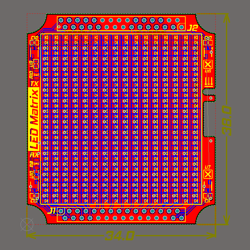 | 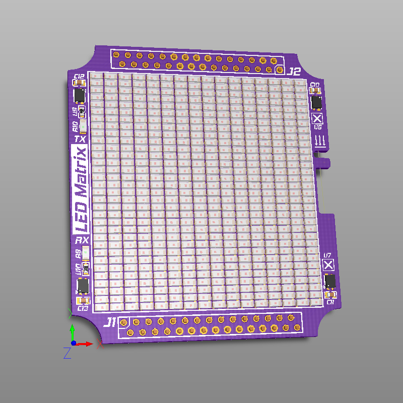 |
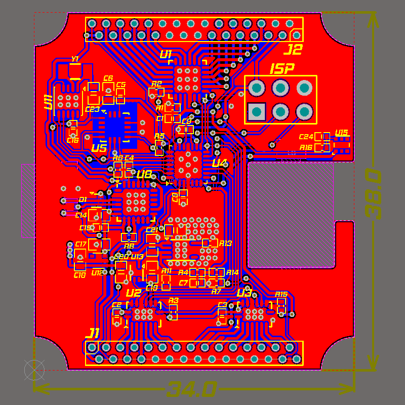 | 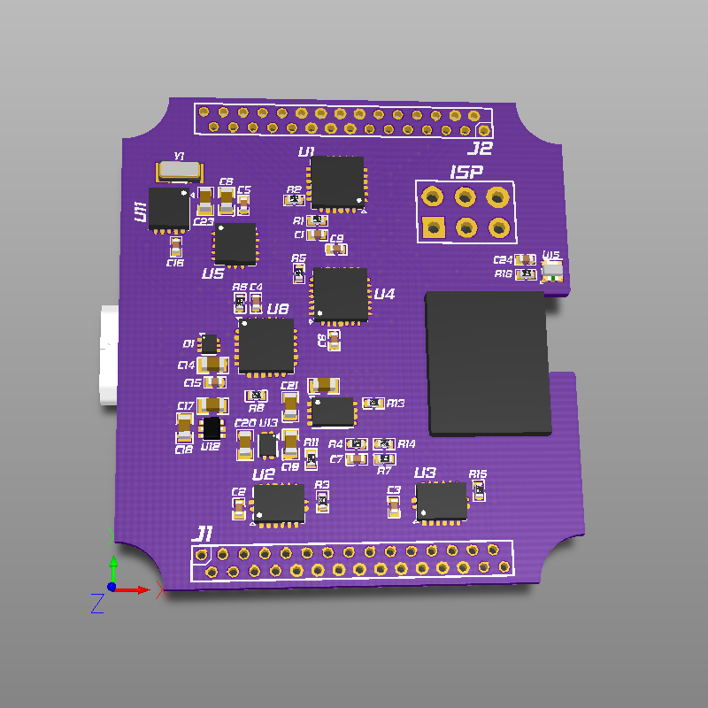 |
Discussions
Become a Hackaday.io Member
Create an account to leave a comment. Already have an account? Log In.