 Yann Guidon / YGDES
I just finished the assembler board !
I had to remove all the diodes and put new ones in the reverse (appropriate) direction.
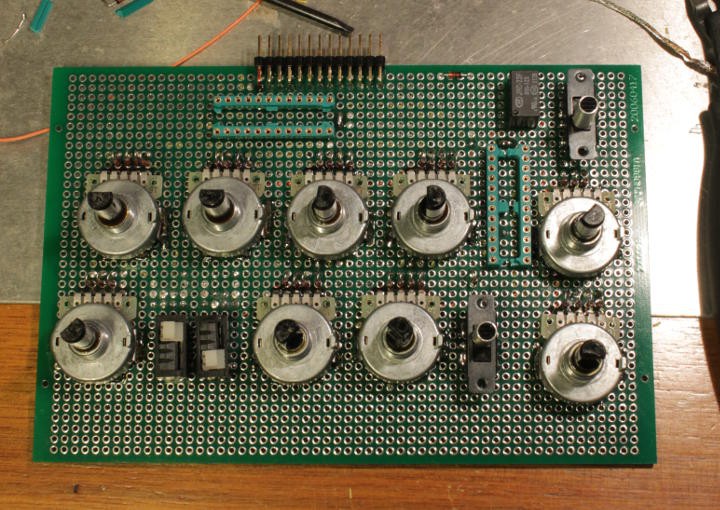
I'll need to label the buttons... but it's a hack ;-)
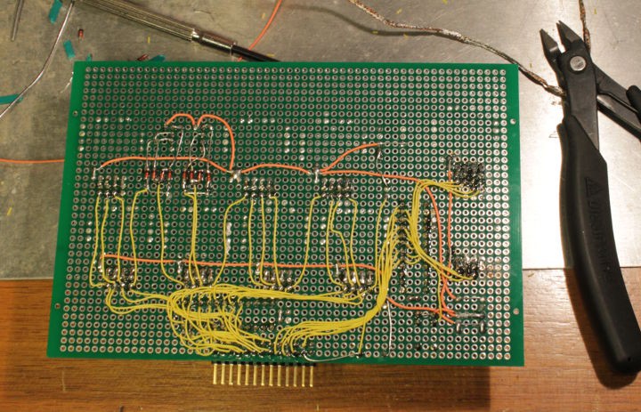
I also wired everything, which makes the other side quite pretty as well :-D
The shift registers are in parallel with the buttons, they are not completely wired because I'm waiting for their delivery. The 2×16 outputs drive the 24 bits of the instruction as well as disable the switches (through the small relay). 7 outputs are still available for other functions. It looks a bit like a mess because I tried to map the pins to the actual instruction bit number. There's no magic there, I should draw some schematic though. One day.
And after all was said and done, I realised I should have put diodes on the outputs of the shift registers...
Too late, I'll just remove the DIP chips from their sockets when they're not in use :-)
But now I have to test the board and the instruction register's latch. This means, prototyping the 3-relays sensor and latch...
Discussions
Become a Hackaday.io Member
Create an account to leave a comment. Already have an account? Log In.