 Yann Guidon / YGDES
So far the instruction format and datapath are well defined and it's time to think about the programming paradigms used by the YGREC.
The architecture does every important thing (as far as I'm concerned) and I notice that it has no opcode.
That's a bit unusual though it's reminiscent of the "Move Machine" ou "Transfert Triggered Architecture". Where the TTA/MM starts operation when operands are available and there are only 2 register addresses, the YGREC has 3 addresses and the operation is immediate.
How should instructions be written ? There are two schools : the algebraic form (used by ADi DSPs) and the direct form (mapping the hardware fields). I like the ADi style (ah, the memories of the SHARC and ADSP2105)
R1 = D1 or T1 SHR (IFZ)but it's more coherent to stick to the representation of the hardware assembler board...
T1 SHR or D1 => R1 (IFZ)
That's where I see that I should swap the ALU field and the SRCX field on the assember board. Too laaaaate... But I can move the ADD/ROP2 button. You will not notice much.
There, I fixed this :
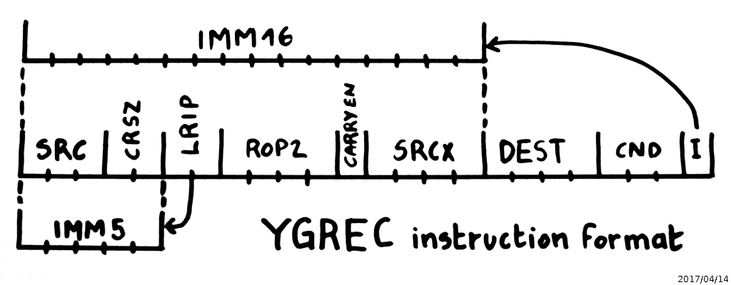
The disassembly board must also be swapped :
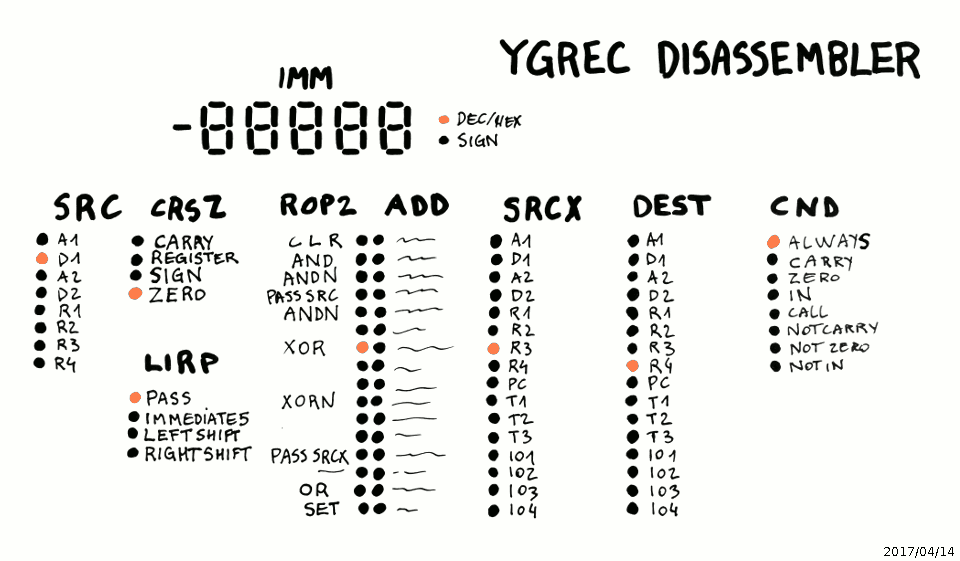
So there, you have everything clearly laid out, just write the code and enter each column in order, and you have your instruction in binary !
Almost in the same vein, there is another question : how to encode NOP ?
Starting with the #YASEP Yet Another Small Embedded Processor I set the following convention:
- NOP is all-zeroes.
- INV is all-ones
NOP does nothing so it should be encoded in a way that does not modify the state of any register. Let's see how each field is affected :
- SRC, SRCX, DEST = 0 should not trigger a memory access. For now 0000 points to A1 and it's not good, so let's swap A1/D1/A2/D2 with R1/R2/R3/R4.
- LIRP : should be in PASS mode, R1 is not modified
- CRSZ field : not affected because LIRP=PASS, but let's say 00=ZERO
- ROP2 mode should be either PASS_SRC or PASS_SRCX. However these codes are assigned to 1100 or 1010 so two bits must be inverted...
- The condition could be "NEVER" if there was one anymore so it's "always", so CND=000="always"
- The Imm flag is 0, which says it's a register source
In the end, NOP is equivalent to
R1 PASS R1 => R1
INV however requires a sort of reset of the program. This corresponds to hitting a place in EEPROM that has not been programmed and reads 0xFFFFFF.
- The Imm flag is 1, which says it's a IMM16 source, which is set to 0xFFFF. Let's use this as the address to jump to and restart the program. A sort of implicit jump vector.
- The condition is 111, which is the opposite of ALWAYS. We don't have "NEVER" anymore but we have "CALL" !
- Call is a bit messy because it swaps the destination register. The result (IMM16=0xFFFF) will go directly to the PC while its old (contents+1) is written to the destination register, which is IO4 for now.
Nobody knows what is hooked to this output register and it'd be a shame if something happened there. This is easily solved by swapping the IO and the T quatuors of registers, so PC becomes 1111.
INV is now equivalent to
FFFFh => PC (CALL)And the new register map is:
| 0 | 1 | 2 | 3 | 4 | 5 | 6 | 7 | 8 | 9 | A | B | C | D | E | F |
| R1 | R2 | R3 | R4 | A1 | D1 | A2 | D2 | IO1 | IO2 | IO3 | IO4 | T1 | T2 | T3 | T4 |
.
Discussions
Become a Hackaday.io Member
Create an account to leave a comment. Already have an account? Log In.