Close
0%
0%

Power On Sequencer bis

Progressively turns your circuit breakers on so they don't trip

Similar projects worth following
This project supersedes https://hackaday.io/project/11681-power-supply-power-on-sequencer

I develop a circuit that prevents overcurrent and keeps circuit breakers from tripping when the mains if first applied.

Large LED projects use many individual switched-mode AC/DC power supplies sporting hefty input capacitors, that create large spikes when you connect them. A simple circuit turns Solid State Relays on, on consecutive channels, to reduce the amplitude of the current surges. The whole system is located in the electricity distribution box, and has inputs for remote control and chaining with more channels, allowing the control of tens of separate sections.

A pure hardware approach is chosen to prevent any dependency on software, better repairability and less points of failure.

(continuing the development started at #Power supply power-on sequencer)

I often work with projects that require a LOT of power supplies and the inrush current is a recurring problem. You have to leave the whole circuit powered at all time because turning it off and on again will trip the circuit breakers. When you operate the large installations that need to conserve power when nobody watches, the waste is significant and quickly adds up in the electricity bills !

There are power-sequencing devices but they are bulky, expensive and hard to integrate "in the field", in the electric dispatch box for example. They are for indoor use and need significant cabling (costs and efforts).

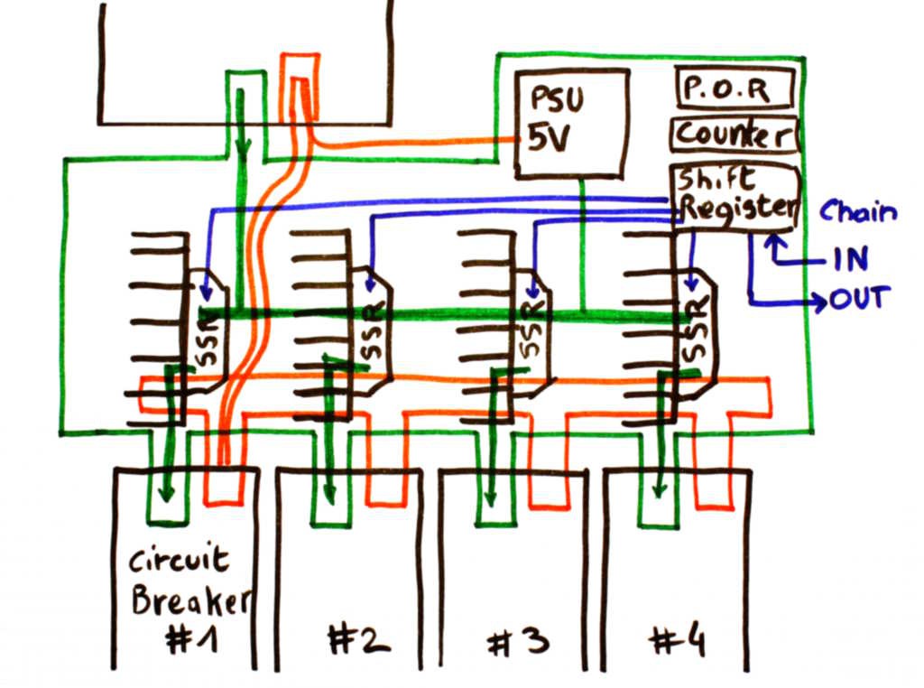
What makes this project different, and the really interesting part, is the form factor : the bare PCB is in the shape of a busbar !

This sequencer can be integrated inside the power box, in a waterproof environment, right at the screws of the safety surge breakers. It is cheaper as well because there is no individual casing, less screws and cabling etc. (expect cheap Chinese knock-offs in 3... 2... 1...)

Chaining ports (input and output) allow several circuits to sequence a lot more than the 4 ports of the basic circuit. The chaining ports can also be used to control the electric supply, read the status of the power or turn it globally on/off. A little trick can also bypass the simple onboard electronics to control the channels independently (but it won't be standalone anymore).


Logs:
1. As seen on another website
2. The PSU arrived
3. surge arrestors
4. Dimensions
5. More parts shots
6. More details about the circuits

  • More details about the circuits

    Yann Guidon / YGDES04/29/2017 at 17:38 0 comments

    So far the description is very sketchy but it takes a while to reinvent the wheel and make it square.

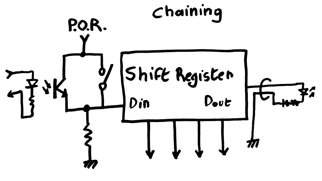
    Here I'll cover the chaining circuit : the shift register is initially cleared and progressively "filled" by the value 1. This value comes from the power-on reset circuit but can also be controlled by an external circuit, through an opto-coupler.

    • In stand-alone mode, a switch connects the P.O.R. circuit directly to the data input of the shift register.
    • In chained mode, an external 5V signal (coming from another sequencer or a programmed controller such as an Arduino or Raspberry Pi board) will control the data-in input.

    The shift register's output is available to the outside, either as feedback to the control board and/or to be chained to the next sequencer's Data In connector.


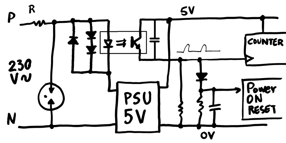
    The mains supply circuit is a bit more complicated because it needs to provide protection, power, clock and failure detection.

    • Protection comes from a fuse/resistor in series with a MOV and/or a Gas Discharge Tube (GDT).
    • Power comes from the PSU module, described before. The output is isolated and floating, for increased safety, yet all I/O are optocoupled (see the first picture).
    • The clock comes from the mains itself. As explained in a previous log, the optocoupler is powered by the drop of a couple of diodes This is in series with the PSU because some current must pass for the LED to work. Whether the PSU will draw enough current remains to be measured though.
    • The failure detection, and Power On Reset, come from the absence of clock signal. Here I have just used a RC network that constantly gets discharged, and charged only when there is a clock pulse.

    This is still far from perfect and I'm not an expert in mains-facing circuits. For example, I have GDT but the Resistor/fuse is still to be determined. Phase detection should be better designed, because the duty cycle depends on the PSU's draw, which is proportional to the output load, etc.

  • More parts shots

    Yann Guidon / YGDES04/20/2017 at 04:11 0 comments

    While I had the camera, I thought it was a good opportunity to show you some more raw parts, introduce you to them and discuss what's in store, and why.


    I already have optocouplers. They're used to extract the clock and eventual loss of AC current.

    CNY17-3 is rated at 5KV isolation, the LED typically draws 1.4V with a current transfer ratio of 100-200% and the NPN phototransistor can sustain 60mA.

    Detecting AC does not require much bandwidth, on the contrary. Not much current is needed either, it will only control a RC network.

    So it might be a bit overkill and may not detect very short losses of power, but still better than counting on the PSU module to discharge through all the parts. The discharge time must be measured, by the way


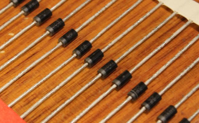
    I got diodes too. A 4K reel of 1N4936, from a time when I used to play the auction game. Starting price was indeed low, I don't remember how much it went in the end but shipping from Canada was far from free...

    But I have quite a lot of 1A 400V diodes. They are used in the primary/input, to shield the optocoupler against reverse voltages and as a sort of Zener.

    I won't use 2 but 3 in series, because the drop voltage has some variability, depending on the current. The remaining voltage will be dropped by a resistor to protect and limit the current through the optocoupler (value TBD)


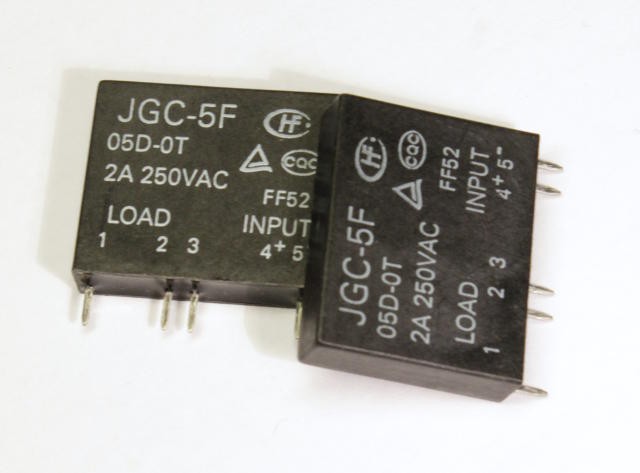
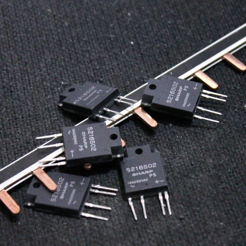
    I have a few SSR to switch the current.

    The JGC-5F here is a 5V, zero-switch relay that is appropriate for small to medium loads. But it's unsutiable for high currents: the 2A are equivalent to max. 500W which is easily exceeded in applications where this project matters.

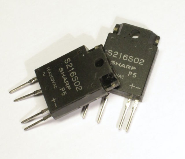
    I employed the tested and trusted SHARP S216S02, that I still have in stock. I don't know where to find more, it's discontinued and I don't know a good and cheap replacement.

    When looking at the full curves and taking into account the derating, the advertised 16A rating is not fully realised without "proper heatsinking", meaning that a dissipator is required if you want to operate up to 50°C. If your electrical dispatch box is outdoors and exposed to the sun, sunrays can heat the insides and affect the parts...

    In the harsh conditions, the part is only safe for 2A. Which is far from the continuous 10A rating of the circuit breaker.

    In a precedent project, I used a dirty solution : use two of them in parallel to provide 4A, or almost 1KW per channel. That was a bad choice, if I believe some weird behaviours. I prefer to use only one with a heatsink, despite the added complexity. I don't have heatsinks yet however.

    Oh, by the way: the pins are fragile. Like, don't bend them. Adding a heatsink will complicate the fabrication. The added challenge is the small pitch : 18mm is not enough to fit the SSR, the heatsink and the required gap to let the air flow...

    Ironically, the SIP package of the S216S02 is about 18.5mm wide so it's not possible to preserve the 18mm pitch. The pitch must be 36mm (to allow the use of classic busbars).

    36×4 channels makes a 144mm PCB : not the smallest possible but I'll miniaturize later...


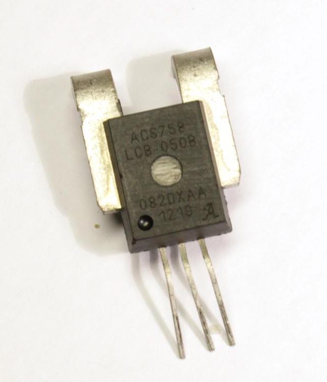
    I also got some AC high-current sensors but they won't be used. The circuit breakers are there to detect the faults.


    Now that I have got the parts and more data about dimensions, it's time to draw the schematics.

  • Dimensions

    Yann Guidon / YGDES04/19/2017 at 15:54 0 comments

    This log continues this one: 3. Dimensions

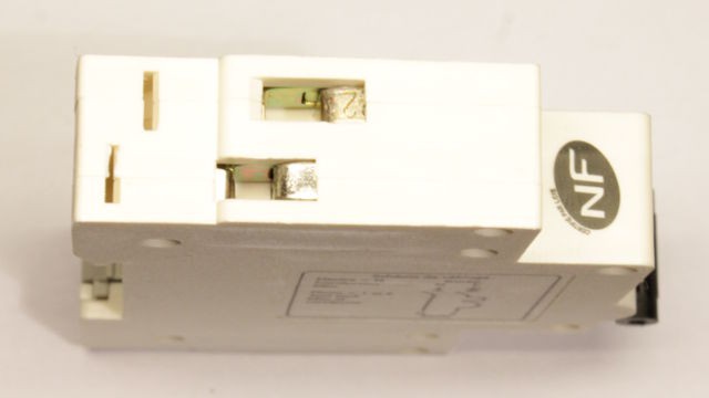
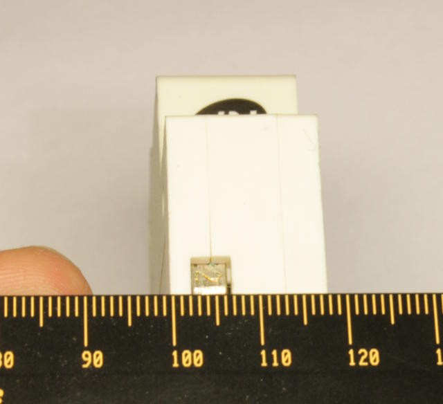
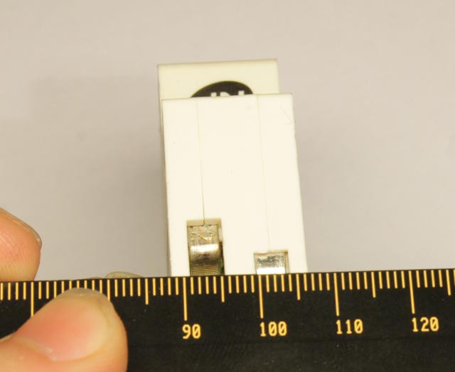
    The main idea of the project is not sequencing, but the shape and dimensions of the circuits that gets directly screwed in the circuit breakers. Here is the top view of a typical circuit breaker, with a perspective of the jaw that usually grips on copper wire:

    The inputs are shifted to ease wiring, in particular with plain, straight copper busbars, such as the one shown in the initial project page's avatar:

    The idea being that one busbar will connect all the circuit breakers in the back of the box, and the front busbar is replaced by a PCB with the SSRs and electronic circuits.

    As mentioned in the previous log, the width is 18mm, the standard of the industry:

    The claw/jaw is approximately 5mm wide but it's better to create a 4mm wide tip.

    The sequencer's supply can be provided to the boards with a sort of thin flat metal wire that will also be screwed in the back receptacle.

  • surge arrestors

    Yann Guidon / YGDES04/19/2017 at 11:06 0 comments

    Spark gaps were mentioned in a previous entry (in the old project page) at 4. Spark gaps

    Spark gaps are a "free" but lousy solution that have bad repeatability and low reliability. They work above some kV, which makes them hardly useful in common situations (like a spike above 400V when a lousy device like an electric drill or a vacuum cleaner is working from the mains)

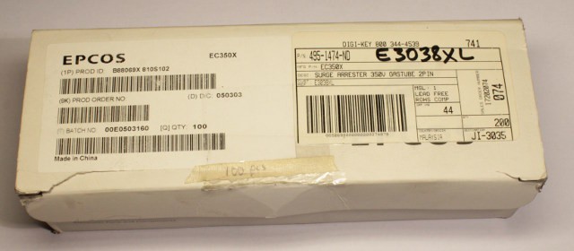
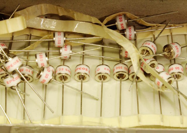
    While looking for other parts, I found a box of EPCOS surge arrestors that I had totally forgotten (leftover from another project). They are rated at 350V and are welcome because the PSU modules have no MOV or other protection device, not even a series fuse/resistor.

    I usually add MOVs to the electrical box, just in case. Now I imagine that my board can also serve as an additional protection to the connected circuits...

    How can I test my PSU and device for high-voltages peaks ? I don't have the suitable testing devices...

  • The PSU arrived

    Yann Guidon / YGDES04/18/2017 at 20:43 0 comments

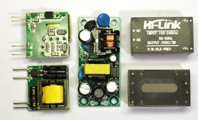
    On the left, the 1W PSU I'll use for the project

    In the middle, a 5W module I've used for another project.

    On the right, a molded/injected version than provides 3W.

    The 1W version is smaller, lighter and is still too large for the small current I'll draw, but it's still a better and cheaper way to power the circuit, compared to a dumb transformerless and unsafe power supply.

    There is no input protection though...

  • As seen on another website

    Yann Guidon / YGDES04/10/2017 at 05:50 0 comments

    Rod Elliott designed a power-on delay at http://sound.whsites.net/valves/ht-delay.html using the same trick as I described in a previous log at https://hackaday.io/project/11681-power-supply-power-on-sequencer/log/55676-latest-considerations

    1. spy on the mains frequency
    2. use the signal as input to a CMOS binary counter

    Rod's binary counter is a CD4020 while I have 74HC4040 but the real difference is in getting the desired signal. He uses the secondary coil of a transformer while I don't have this luxury. The PSU is a small 1W AC/DC that uses a diode bridge at the input.

    The solution I am considering now is an optocoupler powered by an old trick I saw in a magazine long ago.

    The optocoupler's LED is usually in the 1.6V range, which is twice the voltage of two silicon diodes in series. The high-voltage diodes can be put in parallel of the opto's LED (be careful of the direction !!) and the whole is in series with the PSU's input.

    The output requires a low-pass to remove anything above 50Hz (there can be nasty parasites around the zero-crossing zone) and then another RC network to control the /RESET of the counter...

    (diagrams are sorely missing, I know)

View all 6 project logs

Enjoy this project?

Share

Discussions

Similar Projects

Does this project spark your interest?

Become a member to follow this project and never miss any updates