 Yann Guidon / YGDES
 This log continues this one: 3. Dimensions
The main idea of the project is not sequencing, but the shape and dimensions of the circuits that gets directly screwed in the circuit breakers. Here is the top view of a typical circuit breaker, with a perspective of the jaw that usually grips on copper wire:
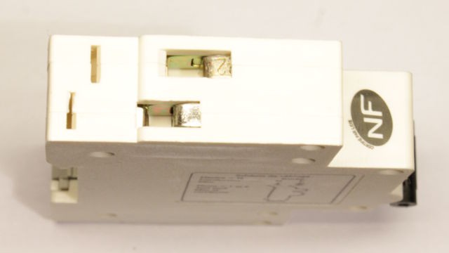
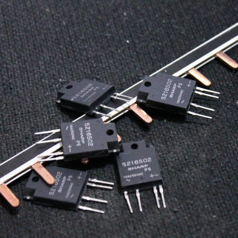
The inputs are shifted to ease wiring, in particular with plain, straight copper busbars, such as the one shown in the initial project page's avatar:
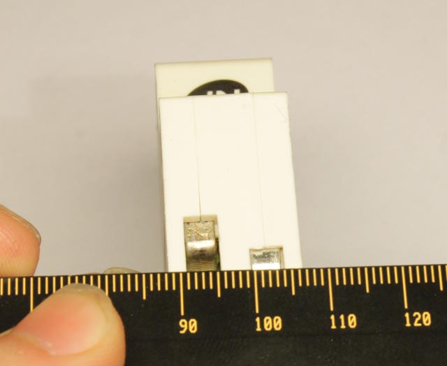
As mentioned in the previous log, the width is 18mm, the standard of the industry:
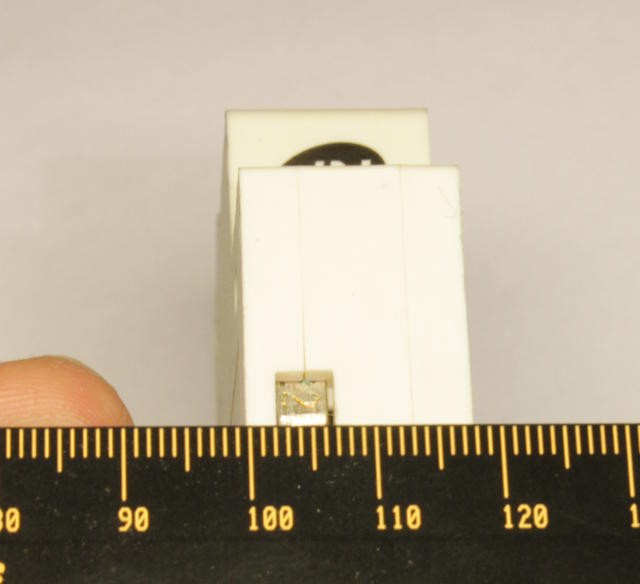
The claw/jaw is approximately 5mm wide but it's better to create a 4mm wide tip.
Discussions
Become a Hackaday.io Member
Create an account to leave a comment. Already have an account? Log In.