0%
0%
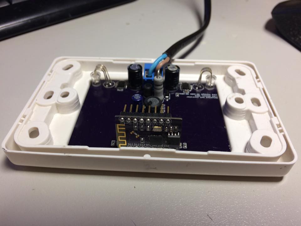
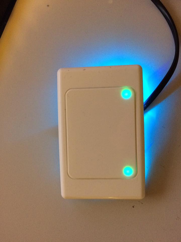
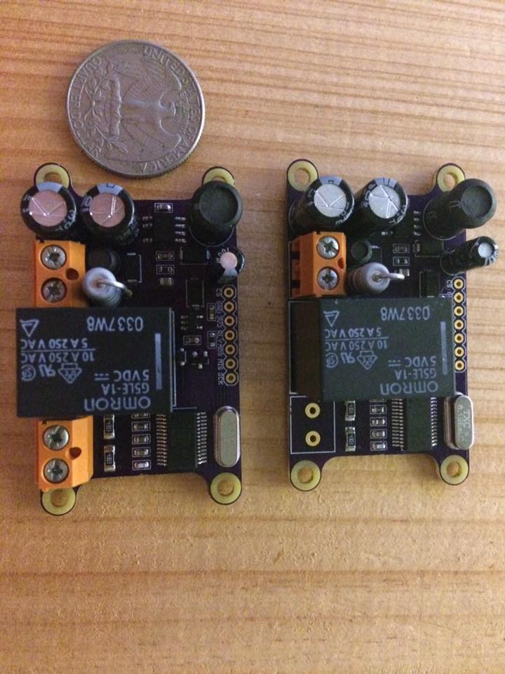
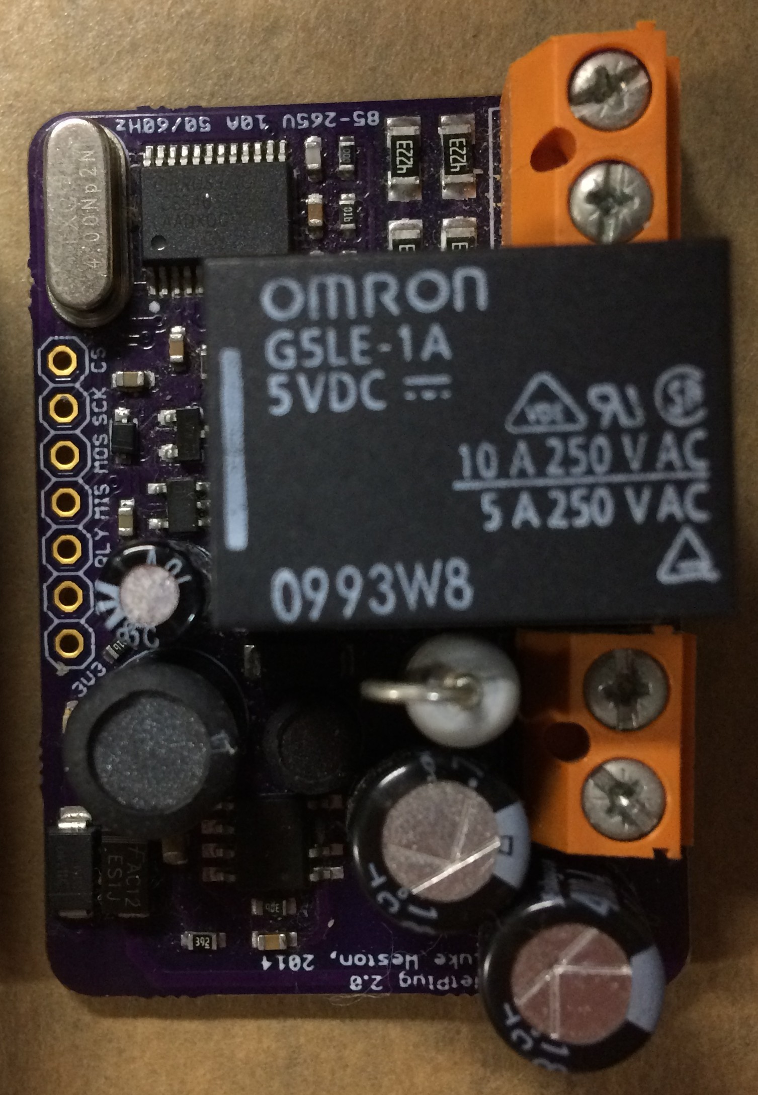
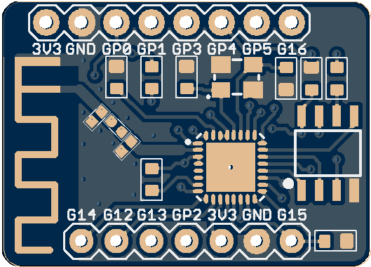
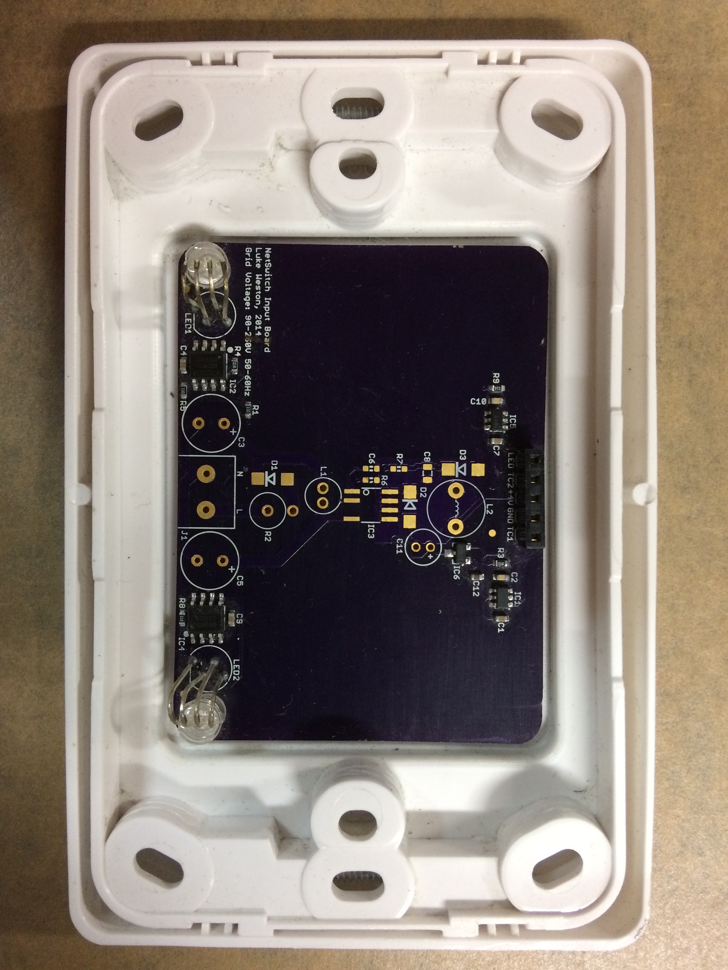
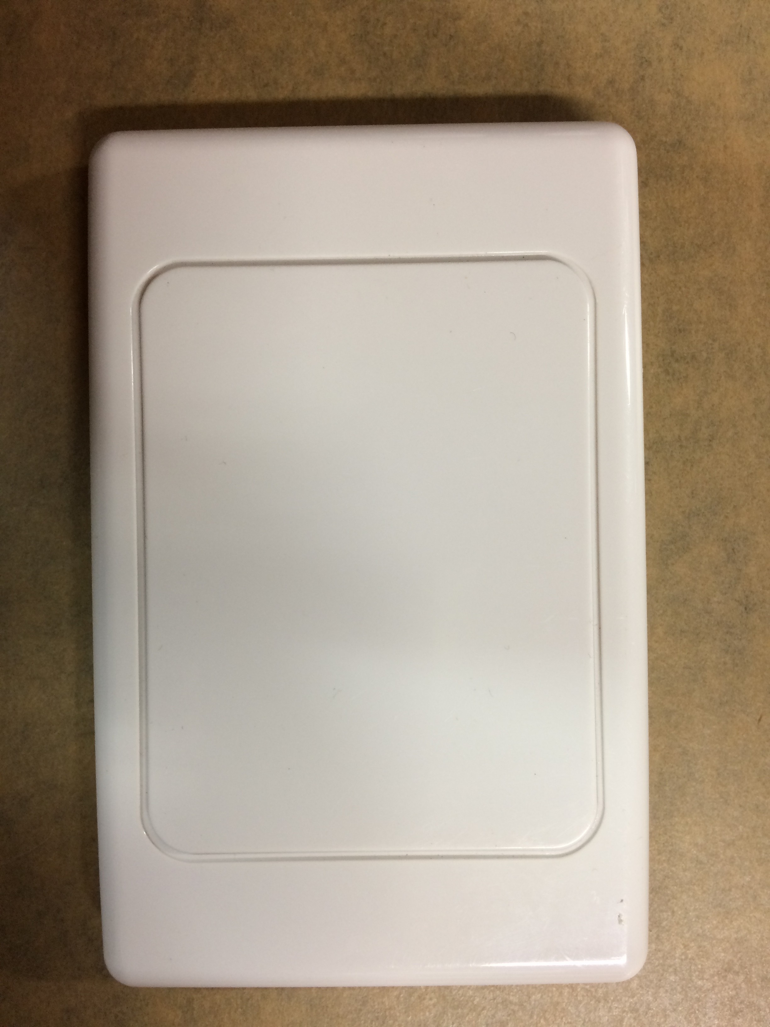
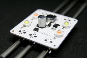
Networked energy metering and home automation
Networked energy-metering nodes (at 10A 85-265VAC) nodes for home and building automation. And smart capacitive light switches, too!
Become a Hackaday.io member
Already have an account? Log in.
Just one more thing
To make the experience fit your profile, pick a username and tell us what interests you.
Pick an awesome username
hackaday.io/
Your profile's URL: hackaday.io/username. Max 25 alphanumeric characters.
Pick a few interests
Projects that share your interests
People that share your interests

 timonsku
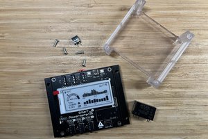
 Jon
Jon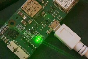
 Heinz-Peter Liechtenecker
 Enrico
Great project!