 Patrick Van Oosterwijck
After hacking on firmware for the past two weeks, I'm happy to report that the prototypes are working!
Here are my two protos: running a Pi 3 and a Pi Zero W:
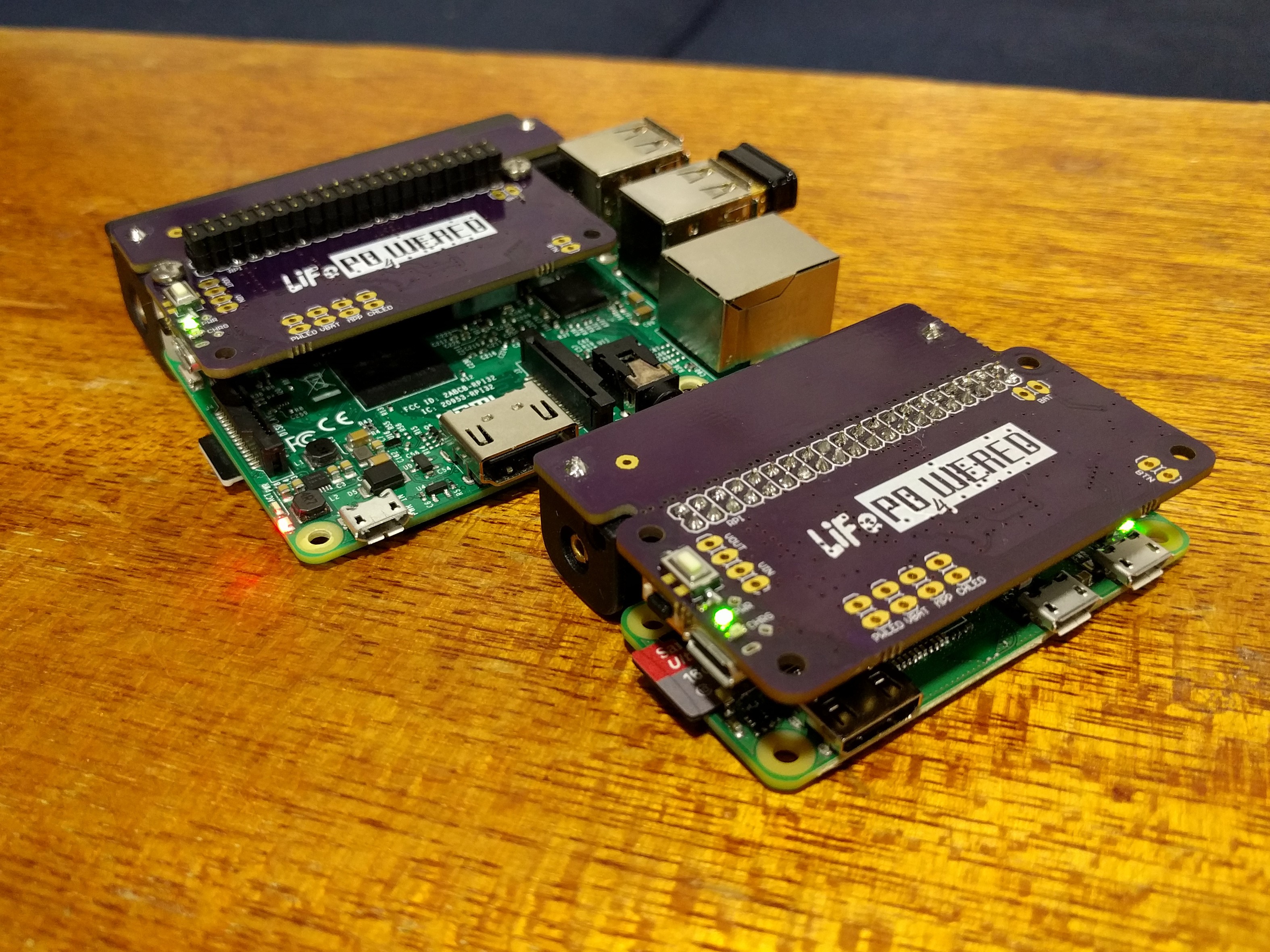
The prototype in the back uses a 18650 LiFePO4 battery and stackable header, the one in the front uses a 14500 (AA) LiFePO4 battery and normal header. To remove the excess PCB used for the bigger battery from the unit with the smaller battery, I had added perforations to the PCB, but I was worried that the copper foil might peel when breaking it off. I decided to see what would happen with and without scoring with a knife, so I scored only part of the perforated area. Here's the result:
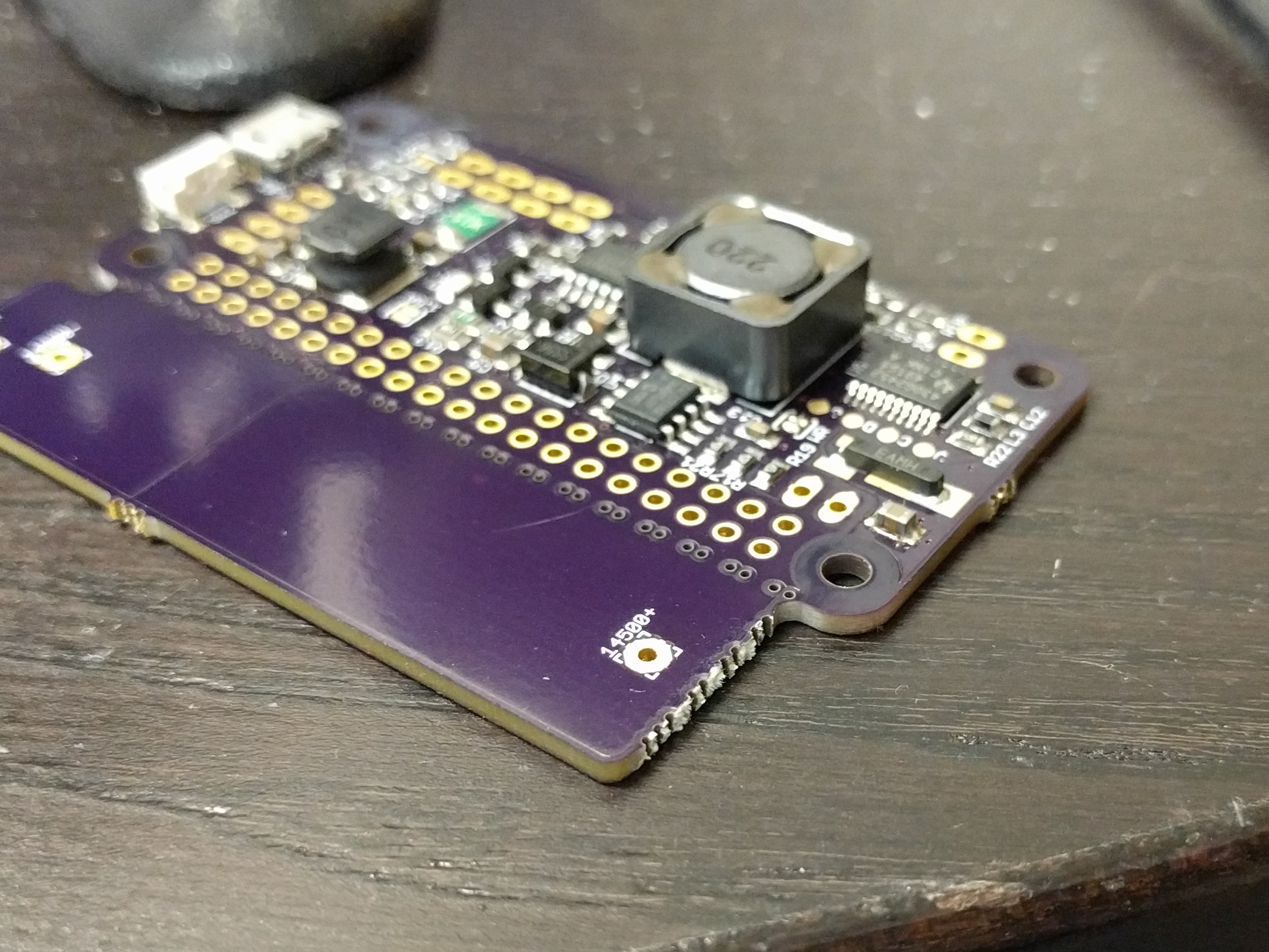
The section of PCB broke off very clean, and I honestly cannot see any difference between the part that I had scored and the part that I hadn't. Very good news! I'll have to see what happens when breaking off the bigger section when I'm ready to build a prototype with external battery.
On the firmware side, I worked on the following:
- Different pin assignments since I had to switch to a 20-pin package to accommodate an extra signal and had run out of pins.
- The extra signal allows measuring the Raspberry Pi current consumption.
- Separate single point calibration values for VIN, VBAT, VOUT and IOUT instead of a single calibration value based on VBAT. Since the range of VIN is now huge (24V) compared to the range of VBAT (5V), the single calibration value wasn't working well.
- Added shadow buffering to the I2C driver. This allows atomic read and write of multi-byte values to prevent race conditions, and will be very important when implementing RTC functionality.
- Timeouts for boot and shutdown phases. At the moment they are hard coded to 5 minutes for boot and 2 minutes for shutdown, but the idea is that they will be settable in 10 s increments. This improves behavior when the Pi is not present or unresponsive.
- Support for mechanical switch (default for LiFePO4wered/Pi+) in addition to capacitive touch. As you can see in the pictures, the prototypes have a side-facing switch as well as a top-facing one. The side-facing will likely be standard and the top-facing an option. There are also pads to connect an external button or cap touch pad.
- Improvements to reduce power consumption when off (still monitoring voltages and button), around 3uA now. Initially I had a problem where the current was ~80uA if the Pi wasn't connected.
Once functional, I could do some preliminary testing, and things look promising:
- With a Pi 3 running at 100% on 4 cores (~950 mA), the board was warm but not hot. This is promising for extra power capability!
- The split sense resistor scheme to allow much higher load current than charge current seems to work! The prototype with the small battery was able to power a Pi 3 @ 100% while also charging the battery quickly, but not above its rating when under low load.
- The 40-pin header with 2 screws seems to be mechanically solid.
Next I'll need to do more detailed high-power testing to see where the limits are. I still need to add registers to set the boot and shutdown timeouts and implement RTC functionality.
Discussions
Become a Hackaday.io Member
Create an account to leave a comment. Already have an account? Log In.