Since I was running out of bare boards from the second production run of 1000, and I was intending to do another run of 1000 built completely at PCBWay, I needed to have a solution for some problem that had popped up in some units from the second production run: the "red light" issue.
"Red light" issue
Some boards were returned because the red CHRG light would come on (though usually very faintly) even if the battery wasn't being charged. None of the units from the first batch of 300 ever exhibited this issue, but either having a different batch of components or just the higher volume made this pop up in a couple percent of units of the second batch of 1000.
For users who mostly use the LiFePO4wered/Pi+ as a UPS the issue isn't really a big deal, but for shelf life and users who use the LiFePO4wered/Pi+ in sleep mode it would be a big deal since it would increase the power consumption in sleep more from around 5uA to several hundred uA. I really didn't want to build another 1000 units that could have this problem, so a fix was urgent.
"Red light" fix
It took a while to come up with a good solution, but I’m pretty sure I figured one out. I reworked 10 boards that had been returned for this reason with my solution, and they all ended up working fine.
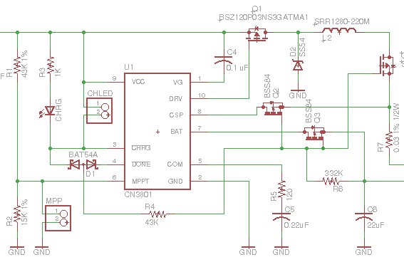
The problem existed in the circuitry I was using to disconnect the charger from the battery when not charging to reduce leakage current. I use three MOSFETs to do this, and in the old circuit they were driven through dual diode D1 from the CN3801’s CHRG and DONE pins:
 In all the LiFePO4wered/Pi3’s and the early LiFePO4wered/Pi+ batch I made, this always worked as expected. The CN3801 has an under voltage lockout at 3.8 V nominal, 3.1 V minimum, and my assumption and experience up till then was that this would keep the CHRG and DONE pins from turning on when the only voltage powering the CN3801 was battery voltage leaking back to this circuit through the diode drop of Q1’s body diode. The pass transistors would be turned off and the circuit would not leak back to the charge input.
But what I’m learning as I’m scaling to higher volumes is that you always run into new unexpected issues as you scale up. When you make 10 prototypes that work great, you will probably run into some 1 out of 20 problems when you make 100 units next. When you have fixed those problems, your next 1000 unit batch will still have some 1 out of 200 problems. And so on. The upside is that the circuit and your yield improves with every step in this cycle until it is high enough you can live with it. Of course, this also depends on component batches etc., so you might have a 1 out of 200 problem even after you’ve done a batch of 300 previously as was the case here.
In this case it seemed that not all CN3801’s would keep their CHRG pins from turning on in the under voltage condition. To be honest, the spec never said that they would, this had been an assumption on my part confirmed by experimentation on an apparently too small number of samples. I have now changed the driving circuit for the MOSFETs to what’s shown below:
 The circuit with zener diode and pre-biased transistor doesn’t depend on variations in the CN3801 anymore. Instead it depends on variations in the zener and transistor thresholds. Which can be just as problematic of course. But I think I’ve calculated the tolerances well enough to be pretty confident it will work as expected. Being based on a current driven device like an NPN transistor with pull-down on the base has the added benefit that it presents a bit more load than the purely MOSFET based circuitry I had before, which could more easily be turned on by small leakage currents.
Thanks to the use of a pre-biased transistor, the new circuit fits where the old one was so from a user perspective nothing will be different in this revision, and hopefully the "red light" issue will be a thing of the past. :)
 Patrick Van Oosterwijck
Discussions
Become a Hackaday.io Member
Create an account to leave a comment. Already have an account? Log In.