 Patrick Van Oosterwijck
My prototype layout is done!
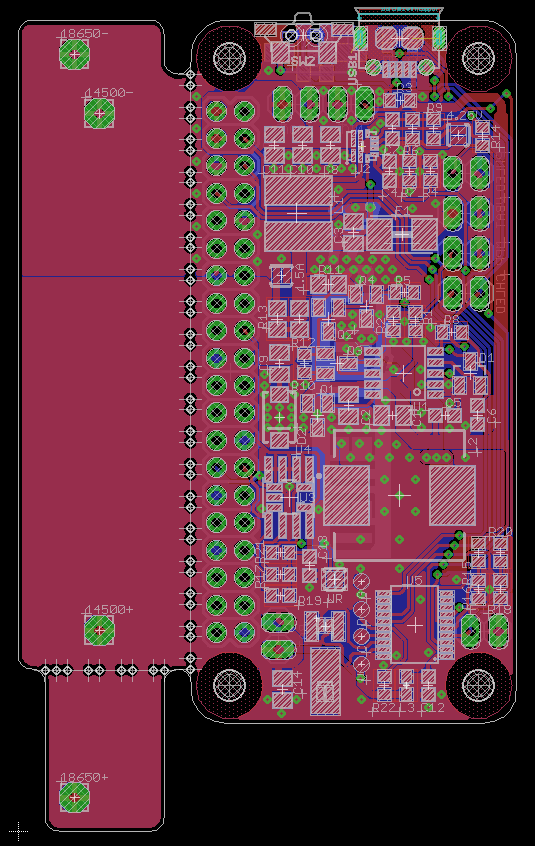
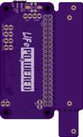
Some OSH Park renderings below:
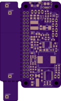
All in all I'm pleased with the result. It was harder than expected to cram it all in, especially the larger (higher current + lower cost) inductors take up a lot of space. This board has the following features:
- Micro USB or through hole 0.1" connections for VIN. Voltages up to 15V should be supported, making it possible to hopefully power this directly from 12V car power or a <15V Voc solar panel.
- Footprint for 3 types of tactile buttons, two on top and one side facing. The idea is to evaluate different button options (only one would be populated). There are also 0.1" connections for an external button. The firmware will likely still support capacitive touch for the external button, but not on the PCB itself, and a mechanical button will be the default. This will likely reduce quiescent current as well below the current <4uA.
- The charge and power LED are right by the micro USB and button, making the user interface nice and concentrated on one side. There are also 0.1" connections to connect external LEDs if desired.
- MPP voltage is adjustable by adding a resistor to the 0.1" MPP connections. 4.65V by default for USB use, but if you use solar you can customize this now.
- Switched 5V output to the Pi (hopefully 2A+) is also available on 0.1" connections to drive external load like a screen.
- The PCB has break-off areas to accommodate either a 14500 (AA) or a 18650 size battery holder, or they can be broken off completely and a battery can be attached to 0.1" connections. Without the battery holder extensions, the PCB is Pi Zero size. The break-off quality is not tested yet and to be evaluated.
- A solder jumper is available to configure either 0.55A (14500 battery) or 1.5A (18650 battery) charge current. The current sense resistor is split to try and implement the higher-load-than-charge current system described in the previous log.
- A solder jumper is available to reduce the output voltage from 5V to 4.25V. The Pi and many peripherals can run at lower voltage and it makes the power system (on both the LiFePO4wered/Pi+ and Raspberry Pi) more efficient.
- An external 0.1" connection for VBAT is available for loads through a 1.5A resettable fuse, but if you use this you need to make sure to manage low battery conditions yourself and draw very little power when the system is off! If loads connected to this are switched from Pi GPIO outputs, it should be fine because they should turn off when the Pi is turned off. But mind the quiescent current, discharging the battery too much will kill it!
- With the new boost converter it should be possible to measure the 5V load current to the Pi and read it over I2C!
- Footprints for several types of 32kHz crystal are present, to implement RTC functionality.
- An EEPROM is present to implement the HAT spec! (Although the physical shape still won't meet the spec.) Hopefully this will result in easier software setup in the future.
Discussions
Become a Hackaday.io Member
Create an account to leave a comment. Already have an account? Log In.