 Patrick Van Oosterwijck
Since blowing out parts on my existing prototypes has gotten them to the limit of their useful life, it was time to get some new prototypes. :)
Time to make some changes related to things I've learned:
- The locations of the mounting holes for the 14500 battery was wrong on the first prototype layout so I fixed that. I also added extra holes to be able to mount the battery with a little gap so it's possible to mount the Pi in a case and have the battery outside. This should work with the official case.
- Breaking the 18650 mounting PCB part off worked fine, breaking the complete battery holder part off was another story. I did manage to break it off, but it put way too much strain on the PCB for my liking.
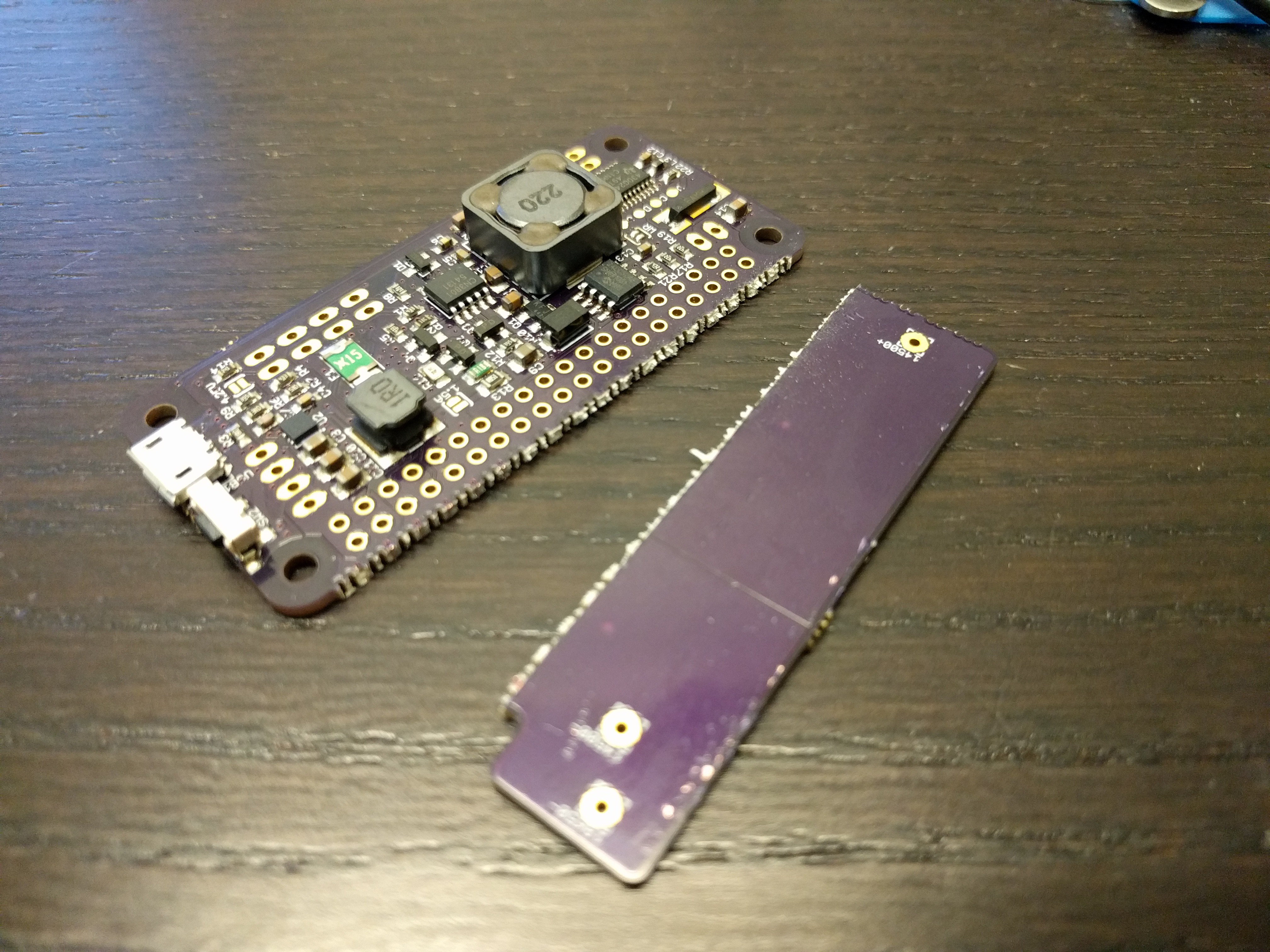
So I now have added a gap that should make this process simpler. Based on demand, I may also decide to have separate panels without the battery holder for those that want to use their own LiFePO4 battery.
- I adjusted the layout around the 32kHz crystal so it now has a ground island and guard ring around the sensitive crystal signals.
- I moved the programming pads a bit farther from the inductor for easier access.
- I added some extra capacitors since ceramic capacitors have the habit of not having their full capacitance under bias voltage, and I want to make sure the supplies are clean. Victim is the 4.25V output voltage option, which nobody seemed to be asking for anyway. Yes, it would allow higher output current, but the output wattage would still be the same. Since downstream there are usually switching power supplies, the lower voltage won't change the available power.
- I changed the micro's supply ferrite beat and capacitor to a small resistor and bigger capacitor. I had observed that under light load the battery voltage had some low frequency noise on it because the boost converter goes to PFM mode, and the periodic on/off puts little dips in the supply at around 30kHz. The resistor / bigger capacitor combination will filter this better.
- The fused battery voltage output was replaced by a battery output switched by load switch. It provides protection and also turns the output on and off with the 5V output. I just was not comfortable with the concept of having people connect stuff to the battery and be responsible for not over discharging the battery. Now the LiFePO4wered/Pi+ circuitry can ensure the battery is not over discharged.
- The charger switching MOSFET was upgraded to a higher power and current device since the current one blew out at high voltage and load current. This required a new footprint.
- I still have the HAT EEPROM circuitry on the board but don't intend to populate it. The HAT standard is completely retarded in that it only allows ONE HAT, and only reads one HAT EEPROM address, even though it uses a bus. This means that if people would use a LiFePO4wered/Pi+ they could not combine it with another HAT. Since most of my customers order stackable headers, many must be using my current products with other HATs and it would be a disservice to populate the EEPROM on mine. But since the LiFePO4wered/Pi+ is intended to be a base for other products that use the full HAT size and add custom circuitry, I'm reserving the space for the EEPROM so it is available for those spin-off products.
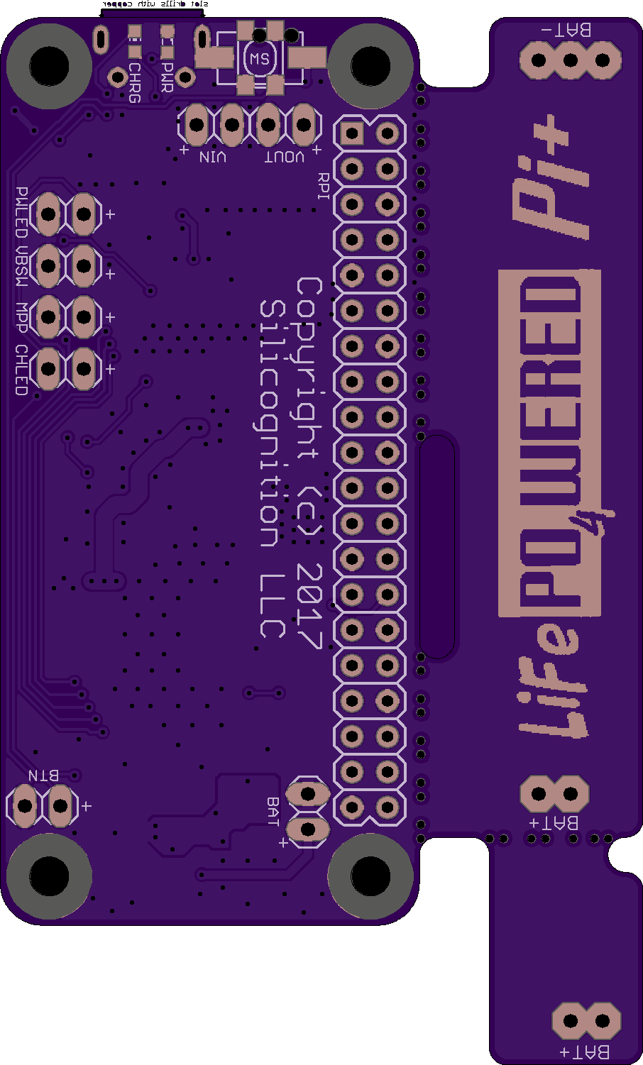
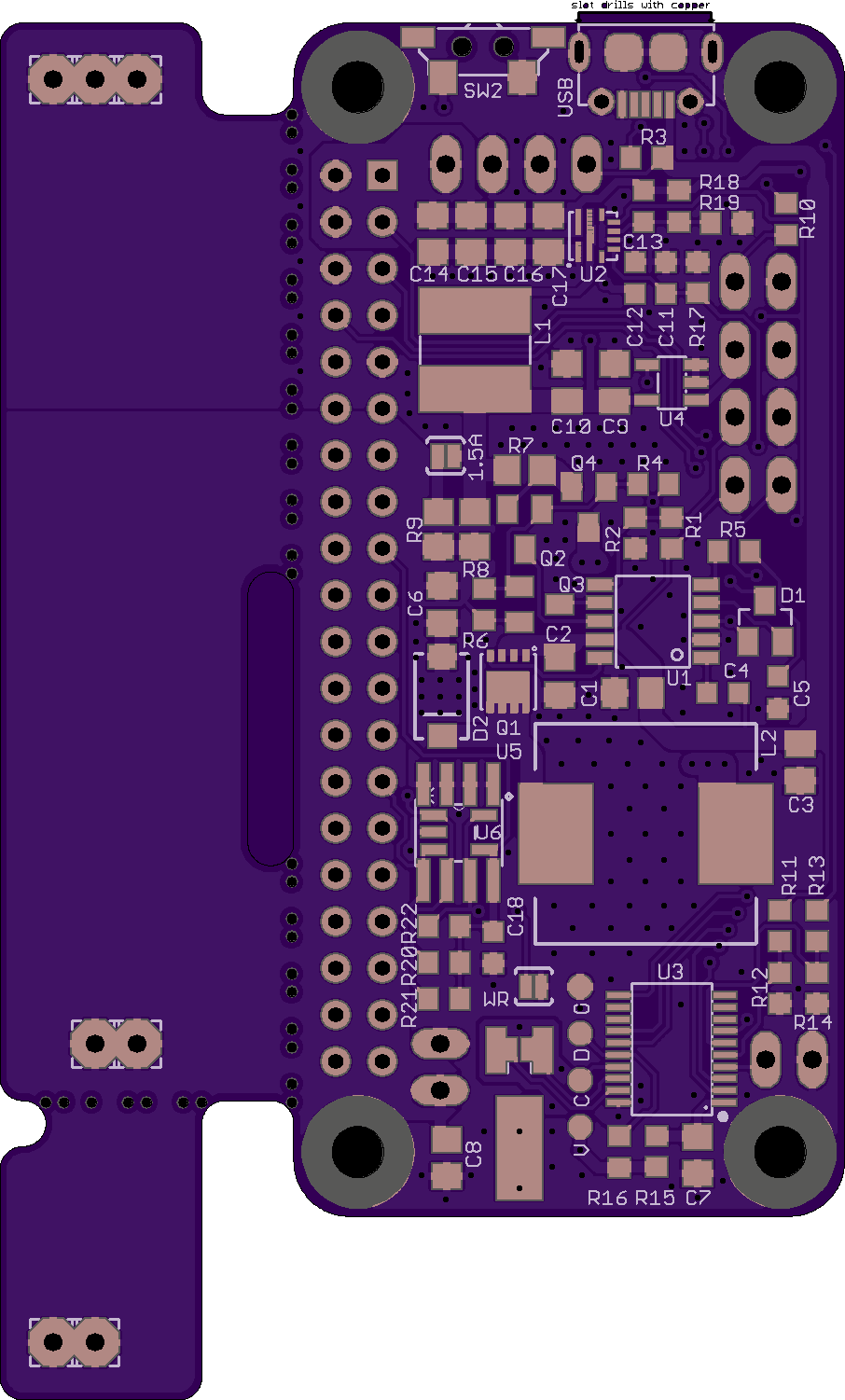
I think that's about it for significant hardware changes. Here's the new layout as sent to @oshpark :
Discussions
Become a Hackaday.io Member
Create an account to leave a comment. Already have an account? Log In.