DESIGNING MY CONCEPT:
- Find or synthesize an antipyretic and anti-inflammatory drug which is absorbed through the skin.
- Find an off the shelf micro piezo pump or design it by myself.
- Design an according PCB.
- Manufacture and populate the PCB.
- Show that my concept works.
Concept drawings:
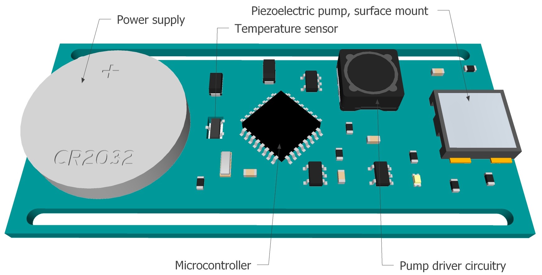
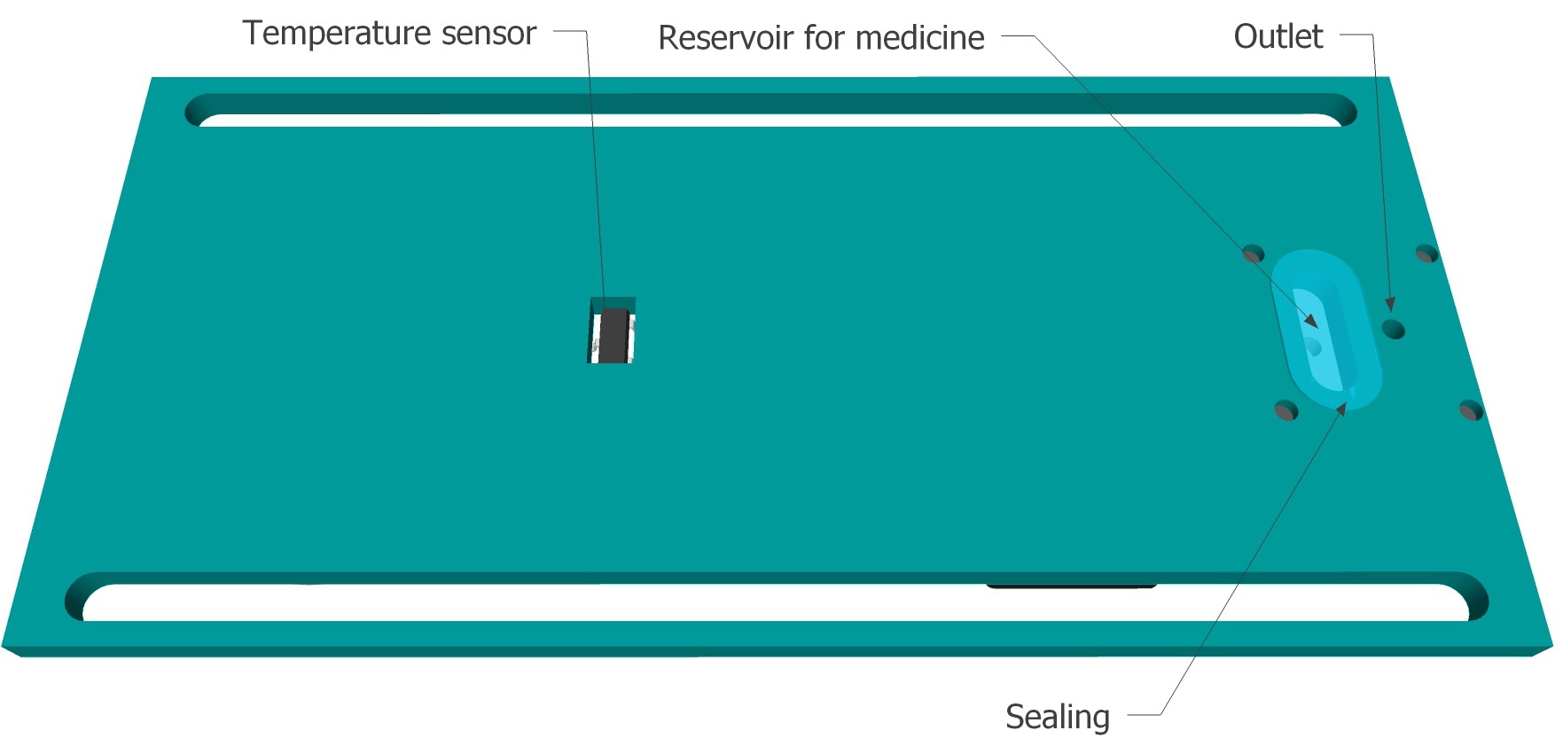
As far as I know the only available surface mount piezoelectric pump is the one from dolomite, but the datasheet is really a disaster. There is a lot of important information missing. I have contacted the company and got a prompt response:
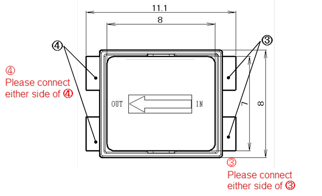
Top View:
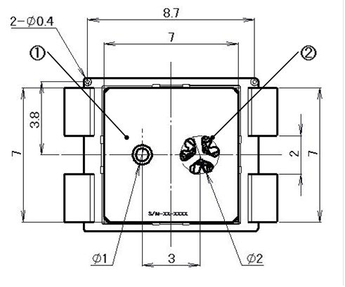
 Bottom view:
 Front view:
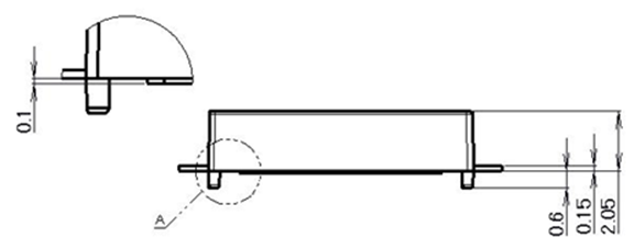 Key:
Key:
|
No. |
|
|
1 |
Inlet |
|
2 |
Outlet |
|
3 |
GND |
|
4 |
VH/VL |
With regards to the Piezoelectric Pump with Surface Mount, the electrodes are paired on the same side as detailed in the diagrams.
One
of the two connections on one side of the surface mount would be used
to connect to HV pad, whilst one of two electrodes on the other side
would connect to the GND pad on the control board. These correspond to
the pin-outs on our regular Stainless Steel Piezoelectric Pumps, these
are specified on page 14 of the technical note.
The pump has been designed to be operated uni-polar. However, the pump can be operated bipolar as long as you keep to the following:
- Standard drive voltage of Piezoelectric Pump is V- = -60V, V+ = 60V
- Voltage more than -60V~100V will be the reason of early degradation
Please do not use with higher voltage than stipulated. With drive voltage more than +/-60V, you have to arrange Offset with no less than –60V. In this case, you cannot operate the pump bipolar.
Microchip provides a Piezoelectric Micropump Driver Reference Design Piezoelectric Micropump Driver Reference Design, which could help me to design a driver. There also a few piezoelectric driver IC's available. And a few other piezoelectric pumps...
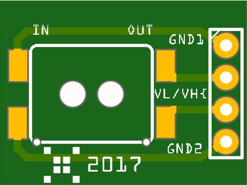
To learn more about the surface mounted piezo pump I designed a breakout board for the pump and ordered an I2C based piezo driver utilizing the DRV2667 from tindie.
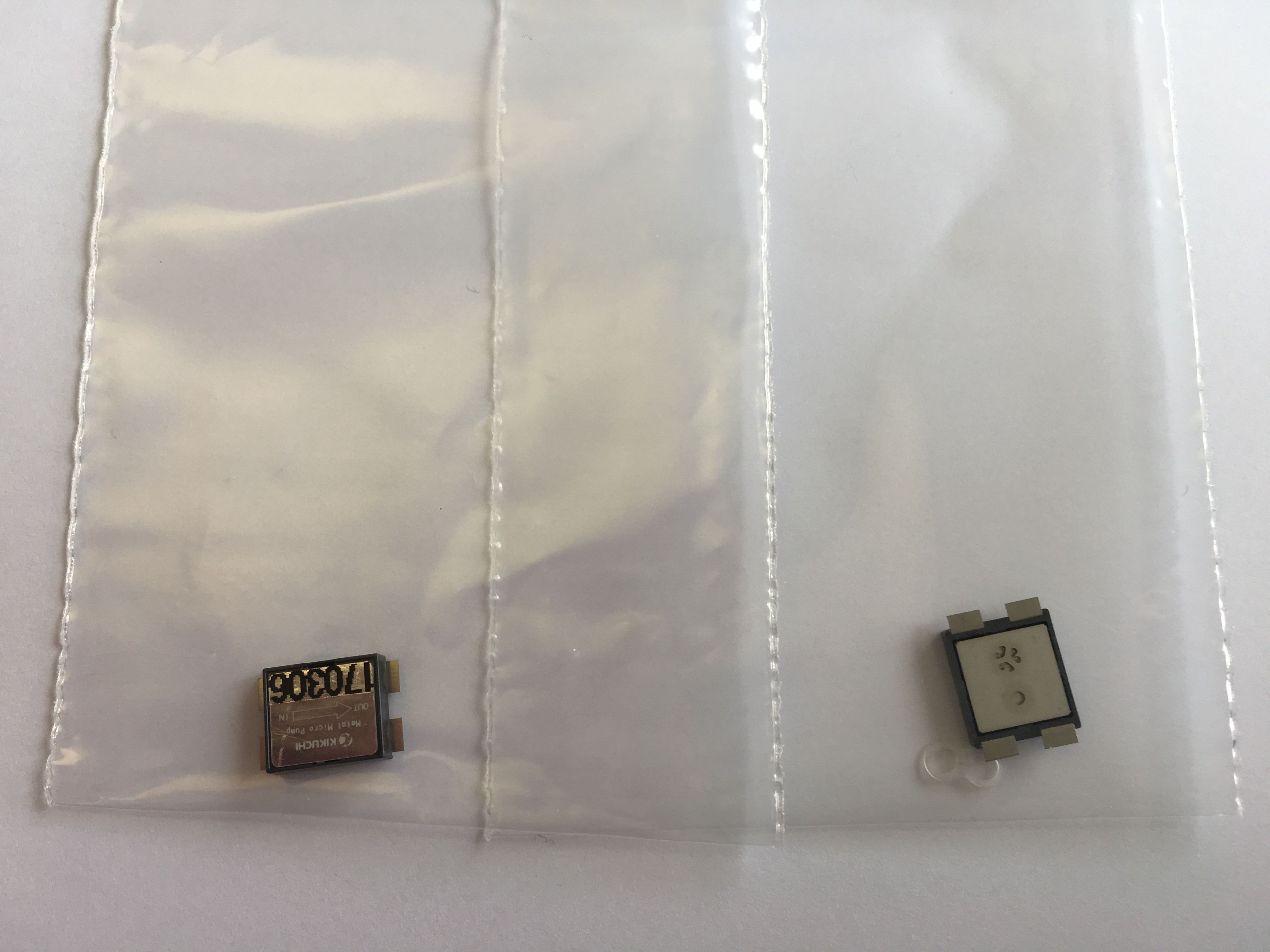
Pumps arrived too:
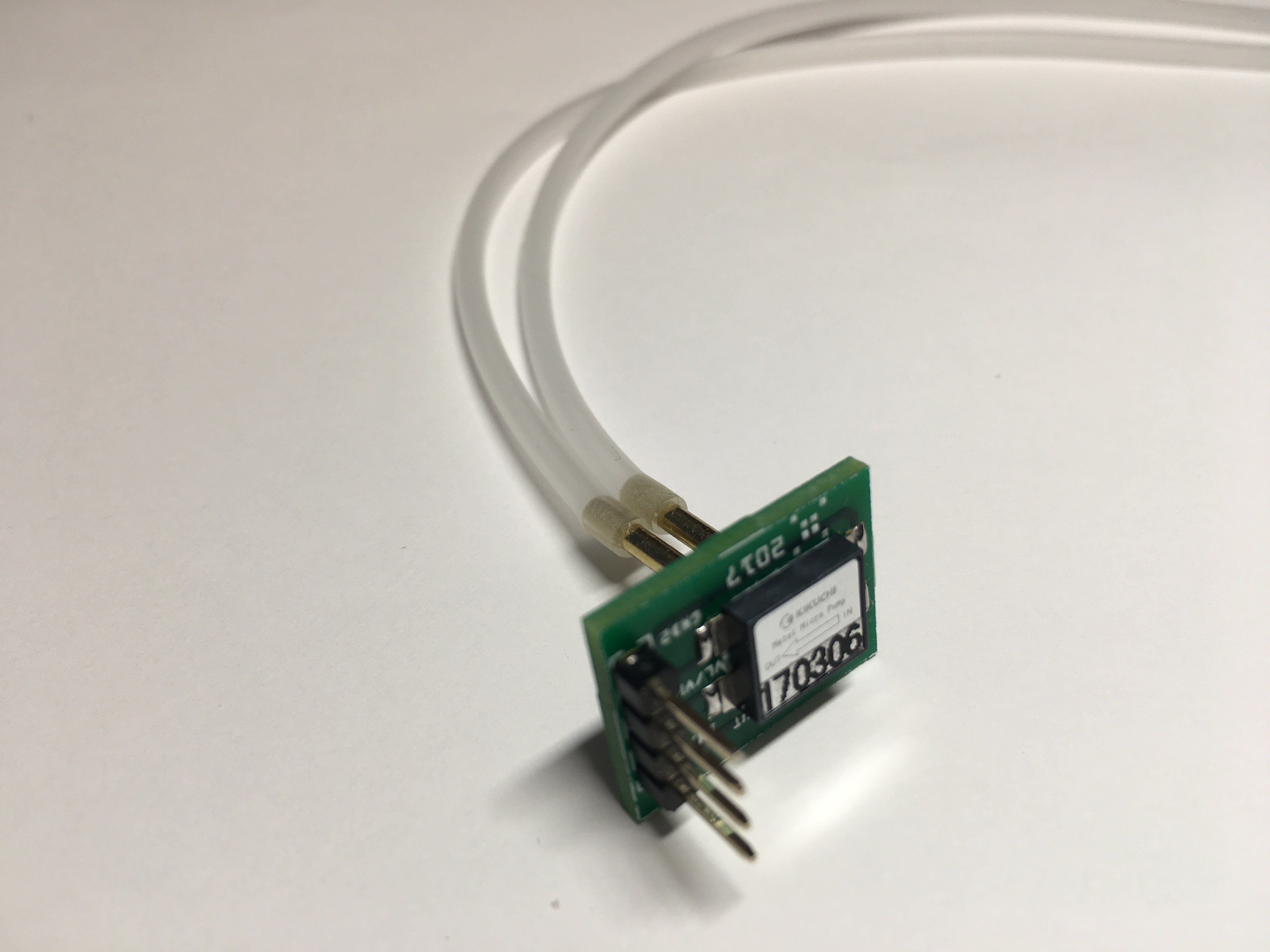
And finally several weeks later the breakout boards to test the SMD pump arrived as well...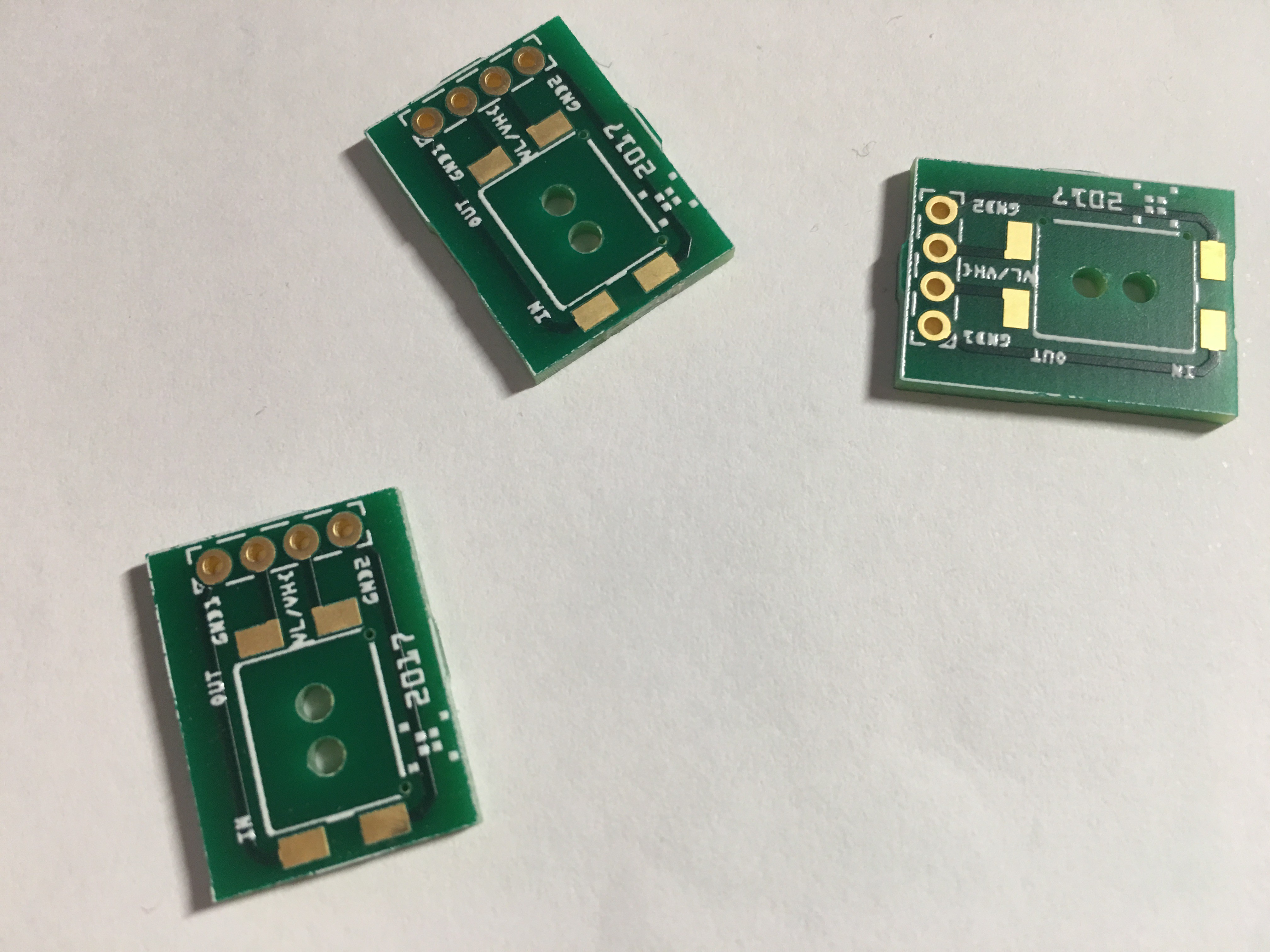
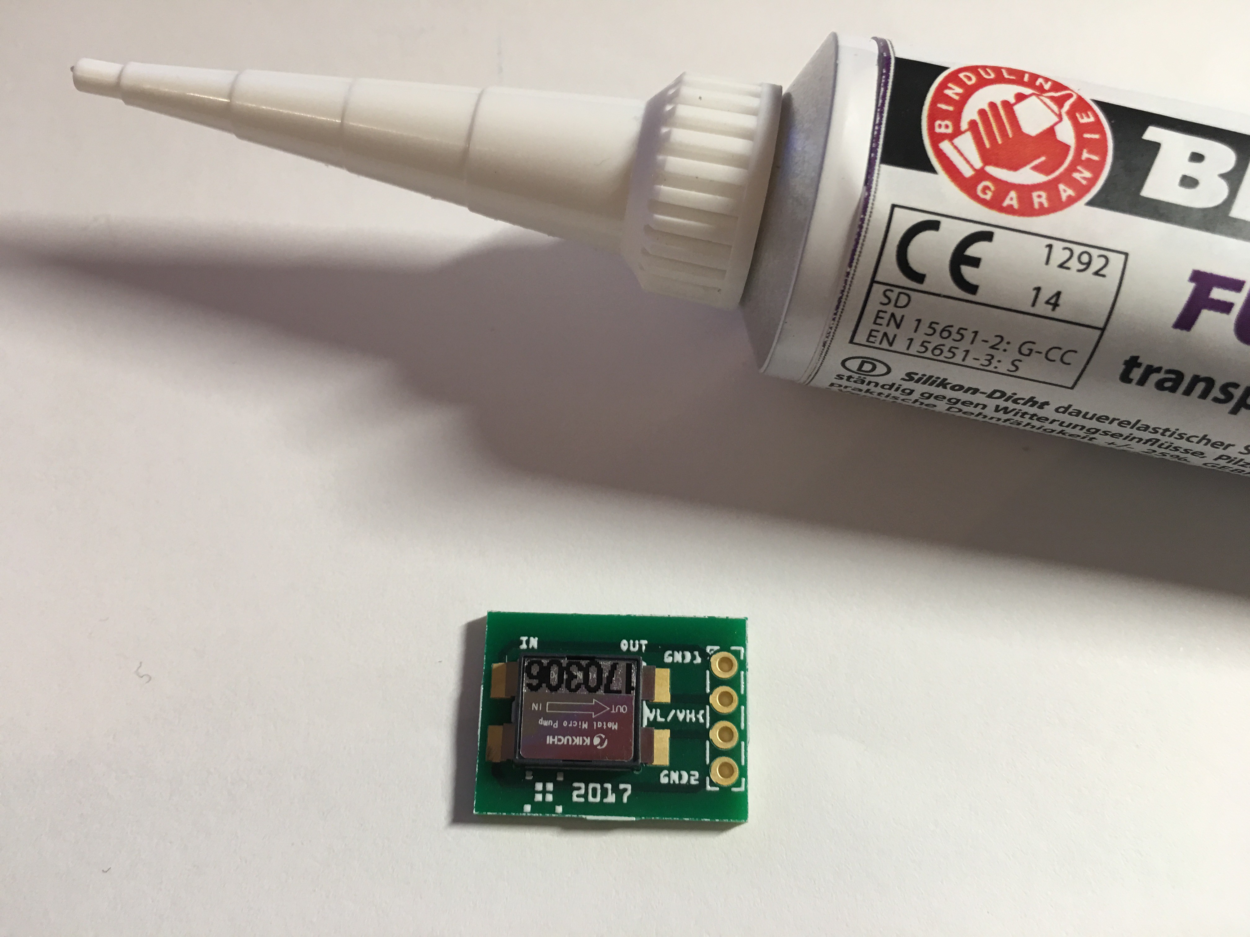
I glued two short pieces of the brass tube with 2 component epoxy resin into the inlet and outlet drill holes of the PCB and attached silicone hoses.
Test schematic...

I used the DRV2667 Arduino library for the test.
Video...
This project is released under the MIT license.
 M. Bindhammer

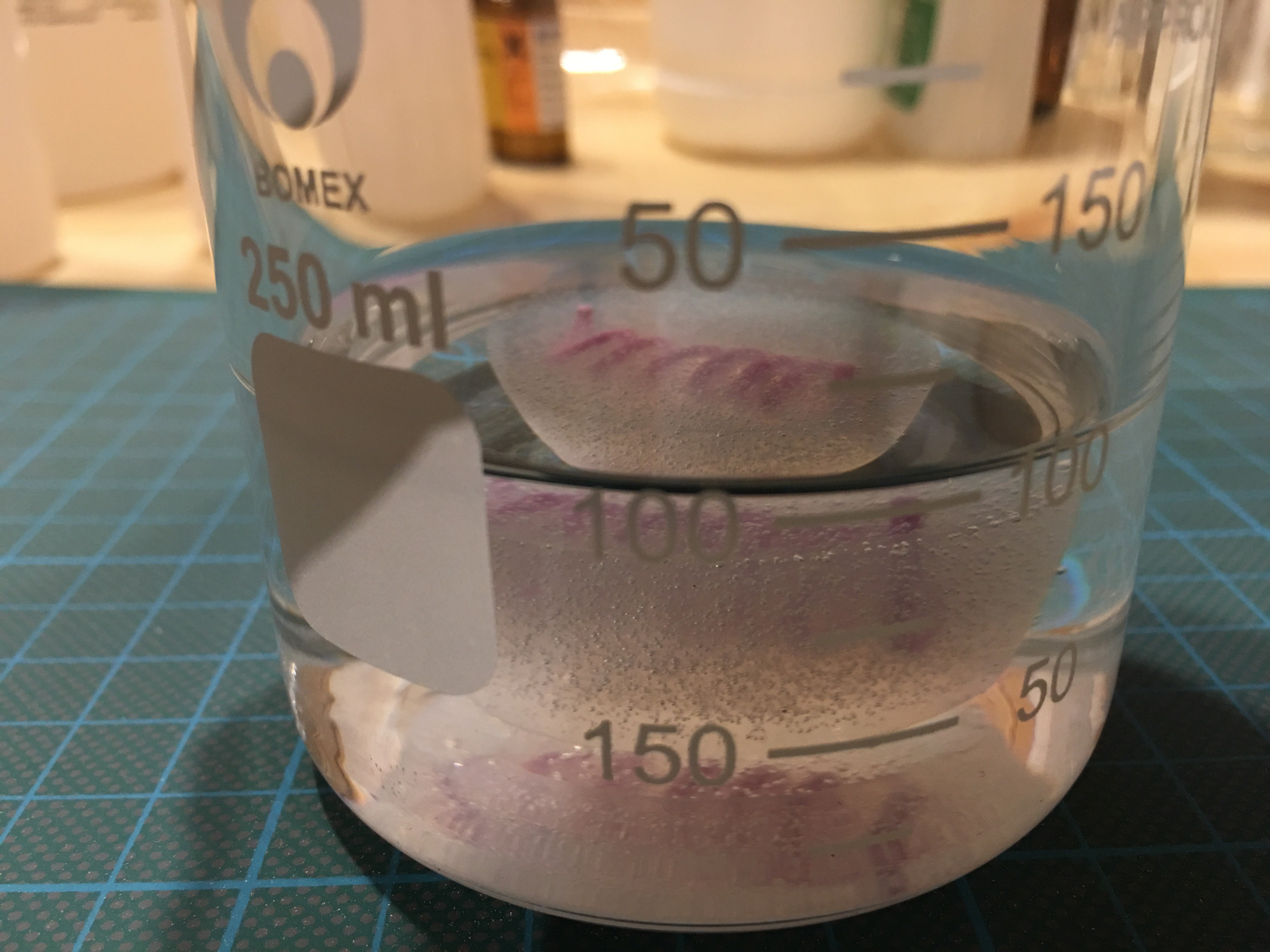
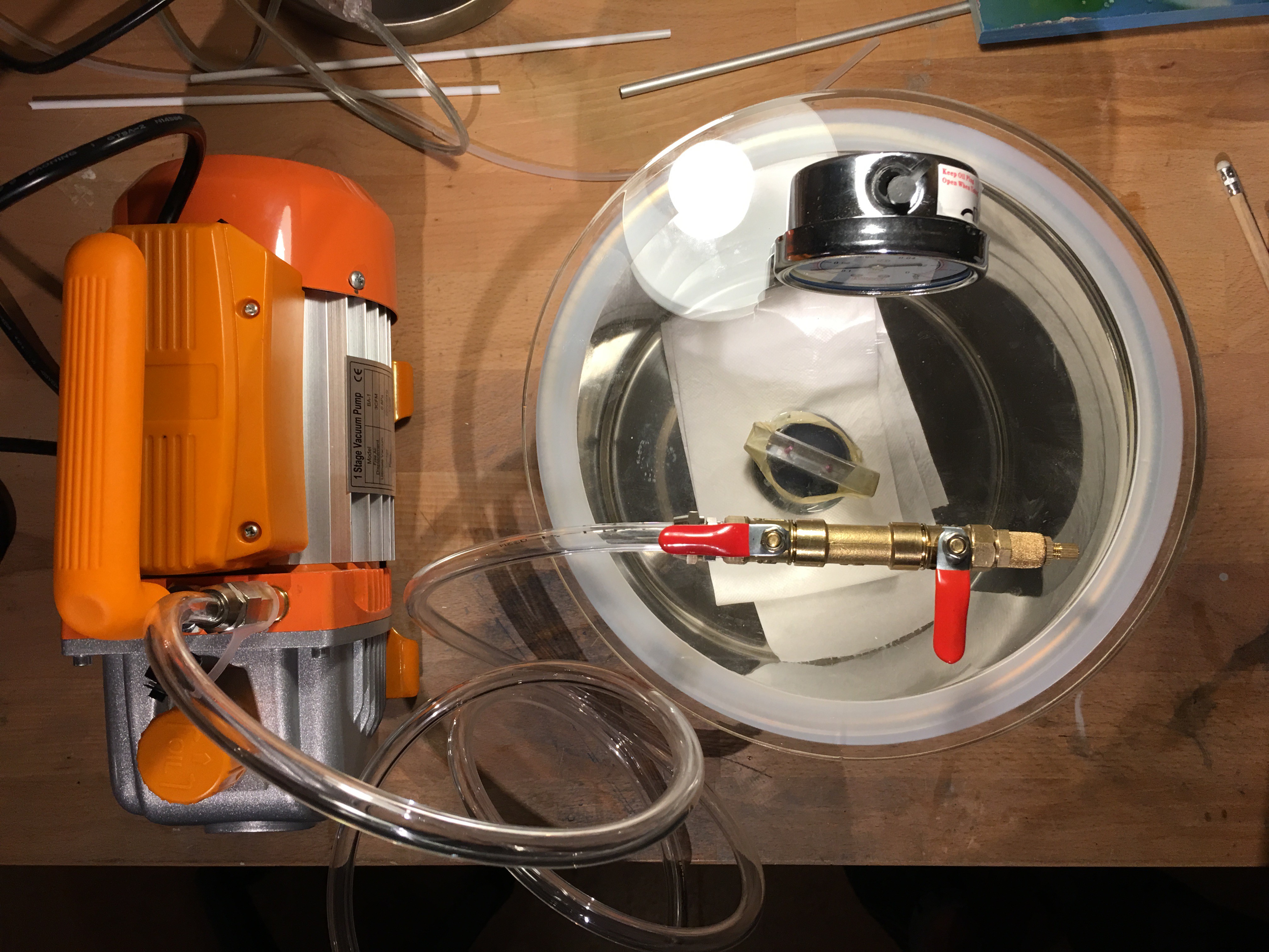
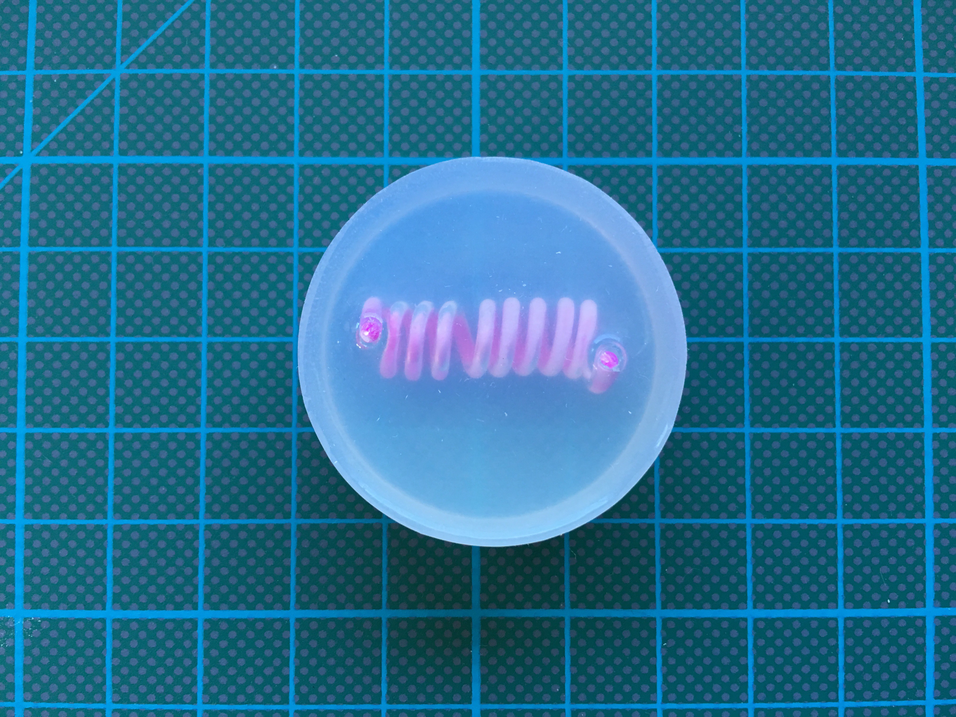
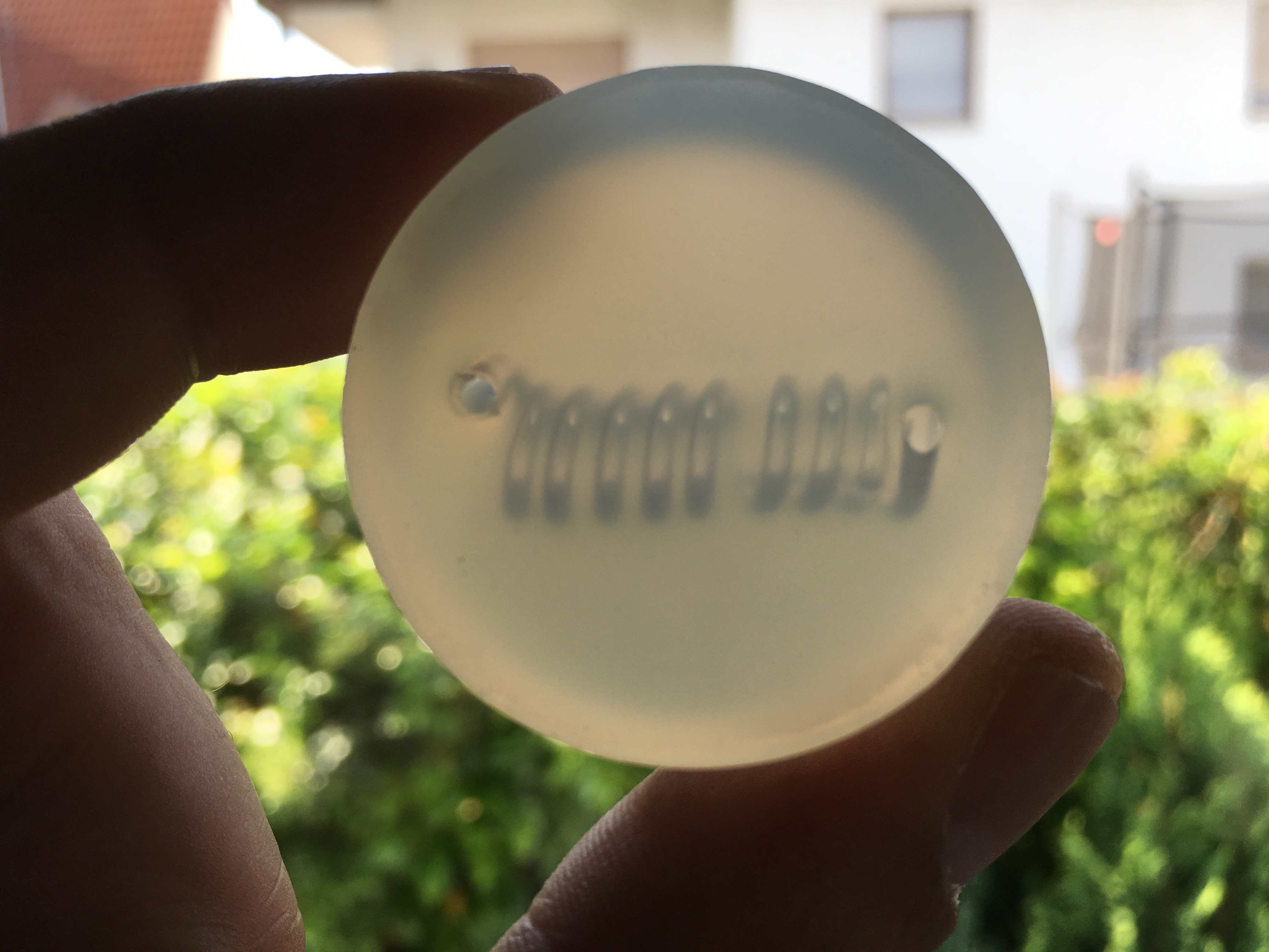
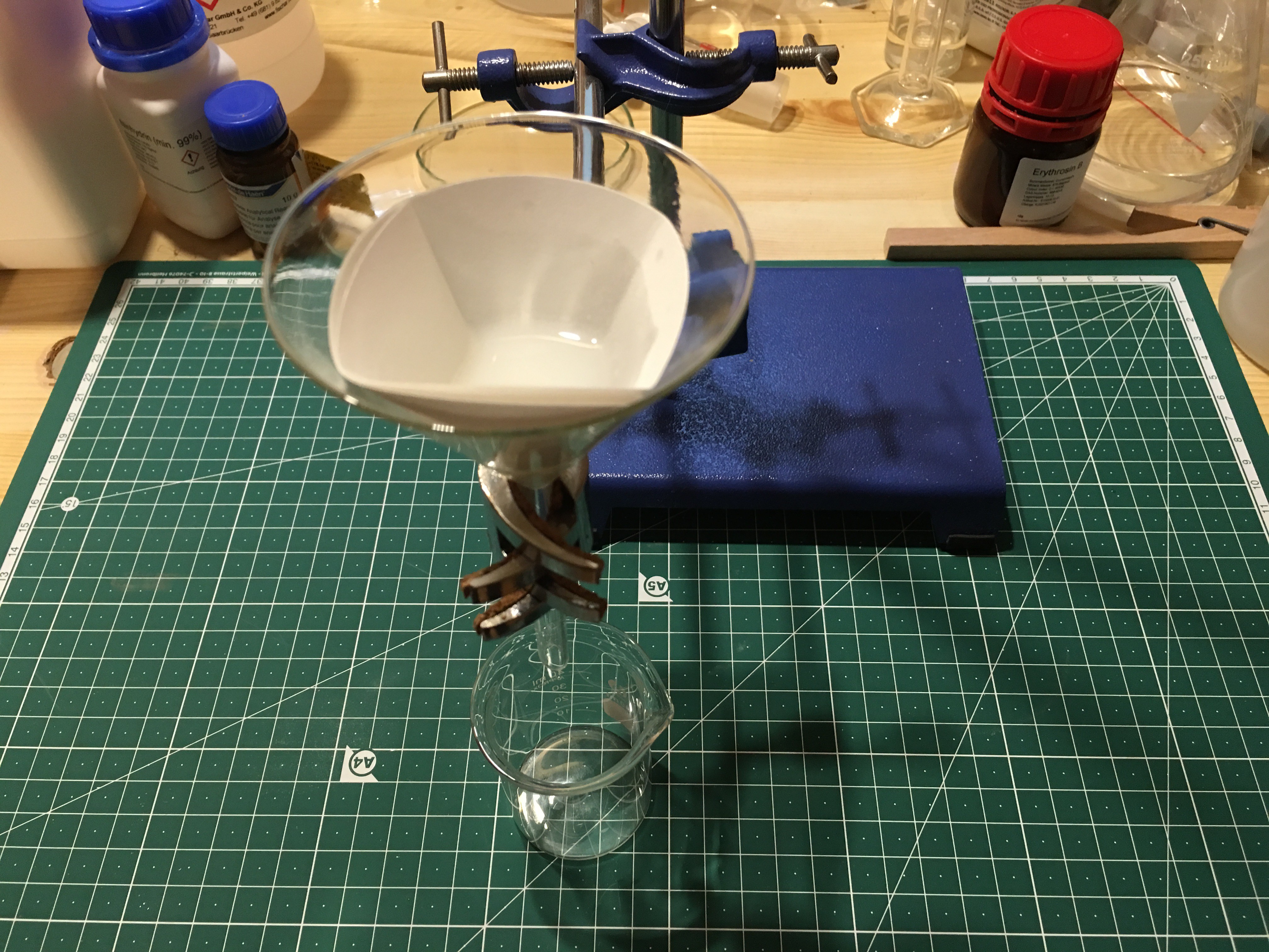
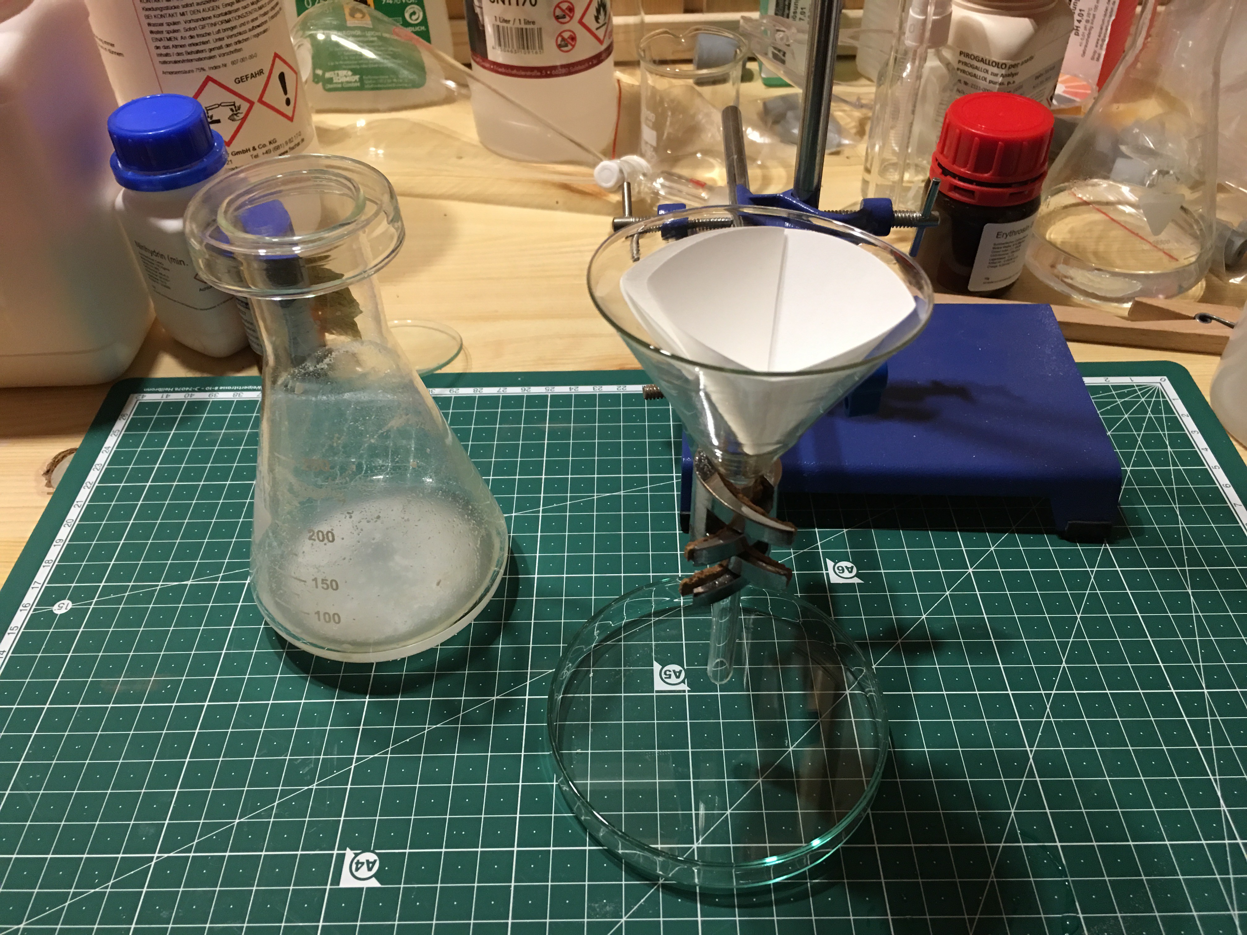 Then I filtered the solution off by adding piece wise another
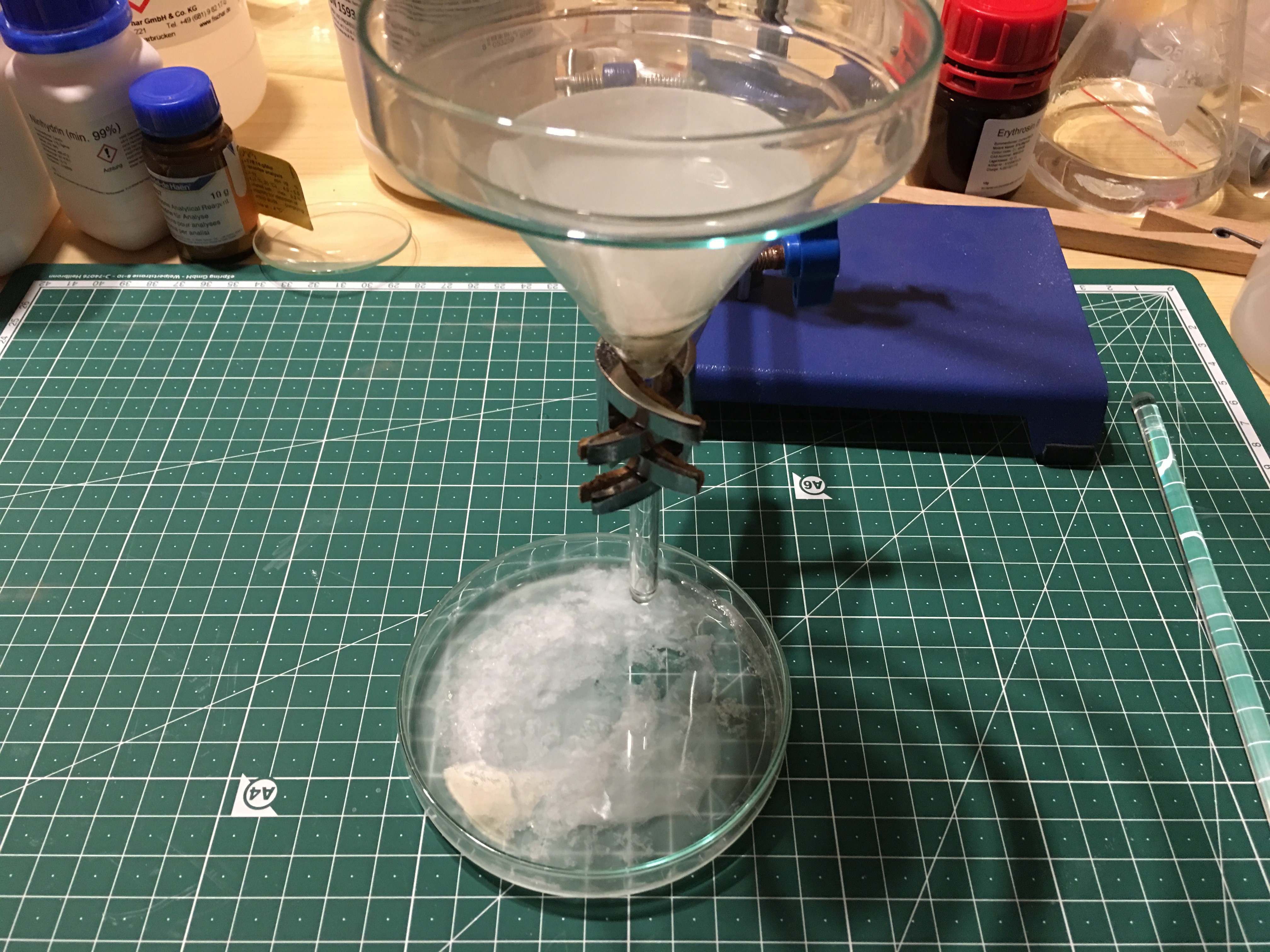
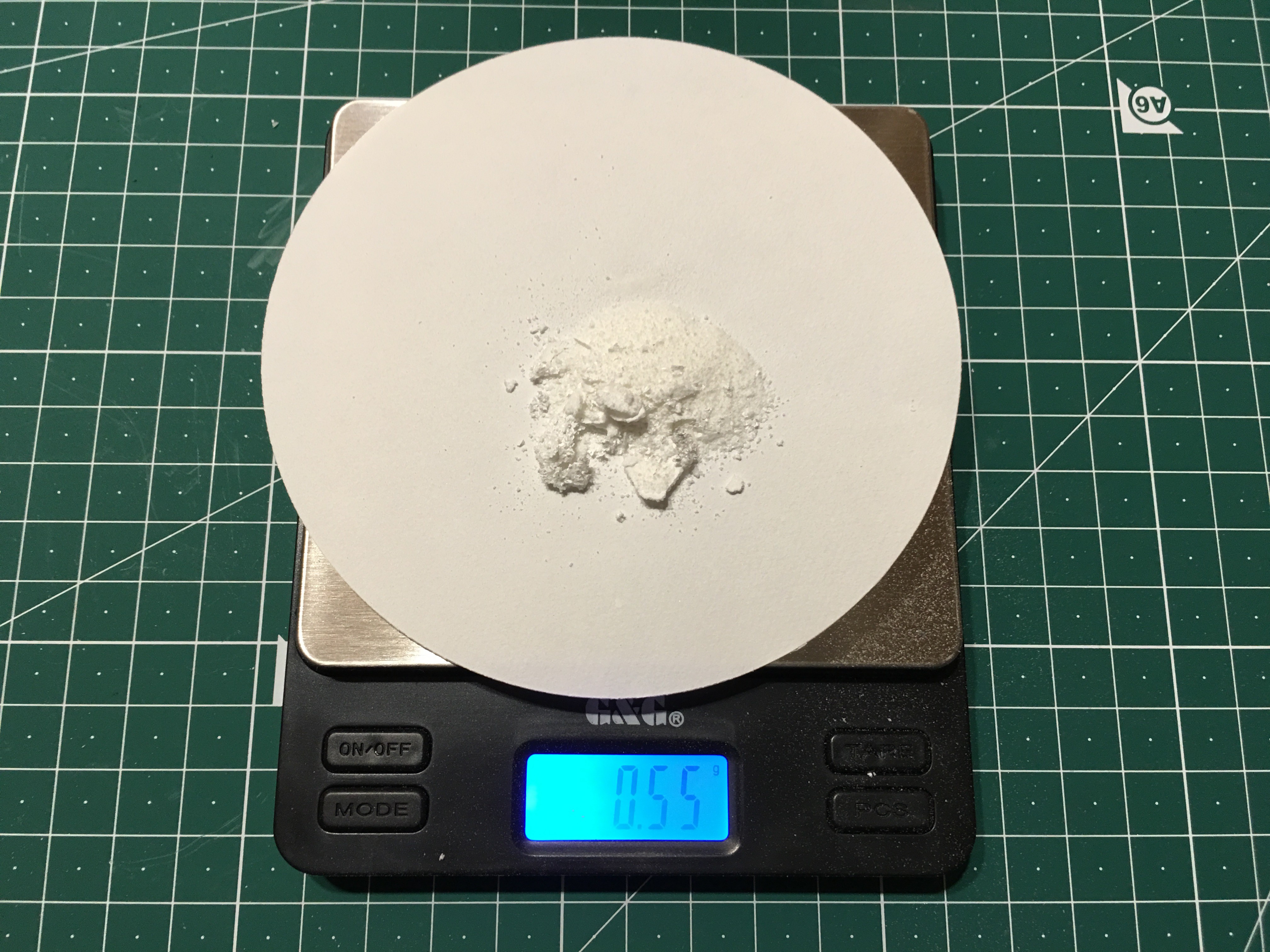
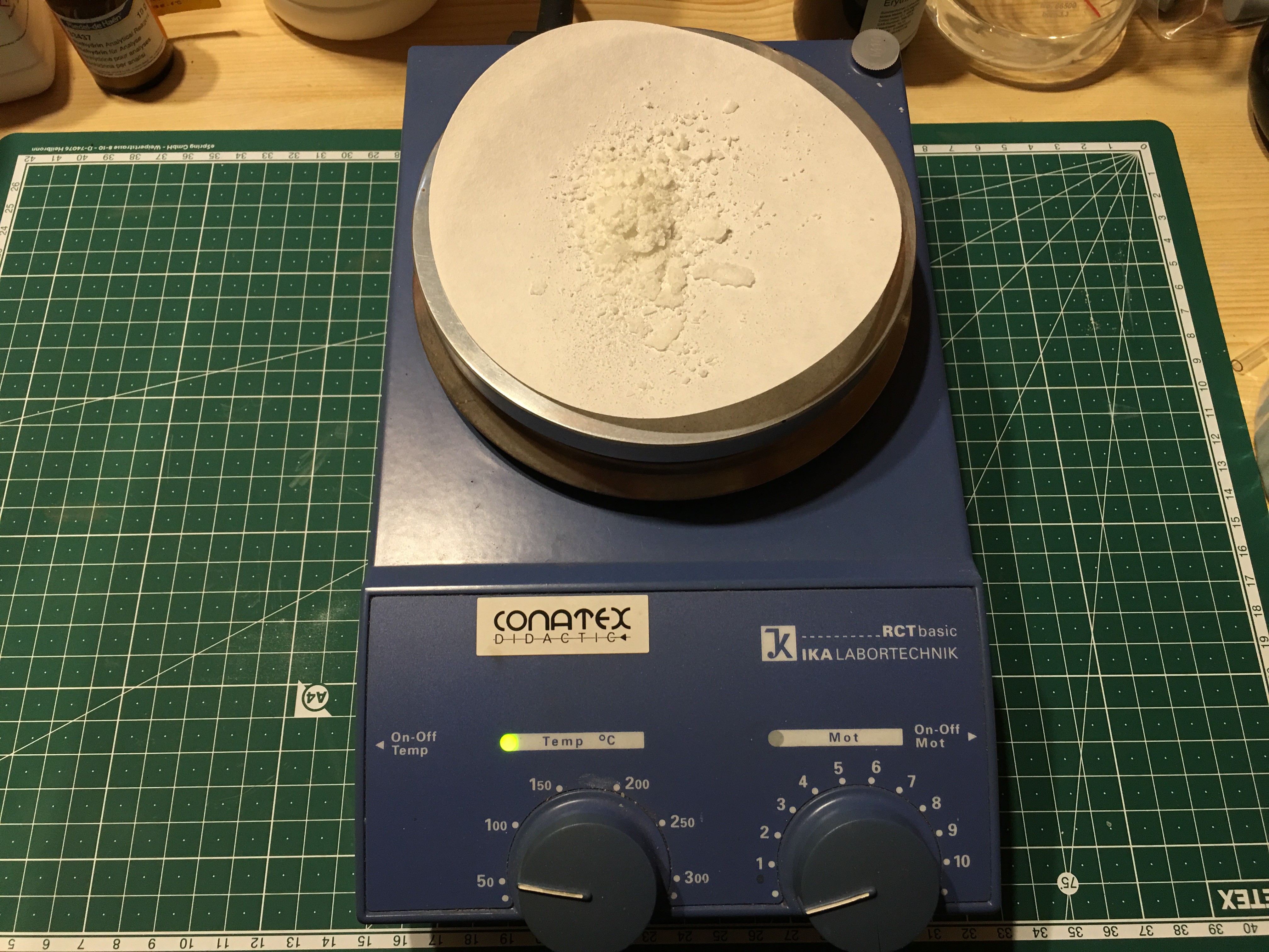
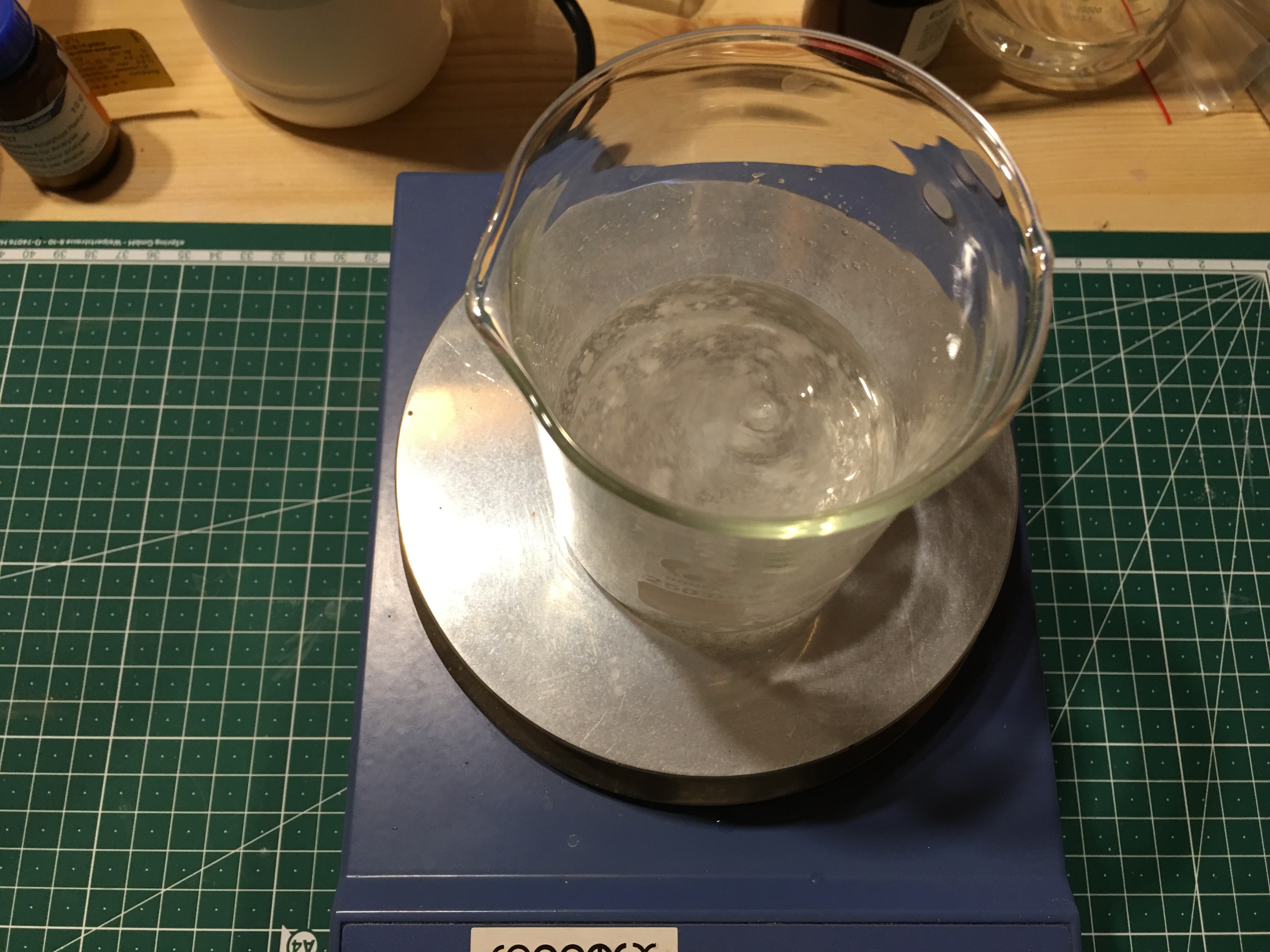
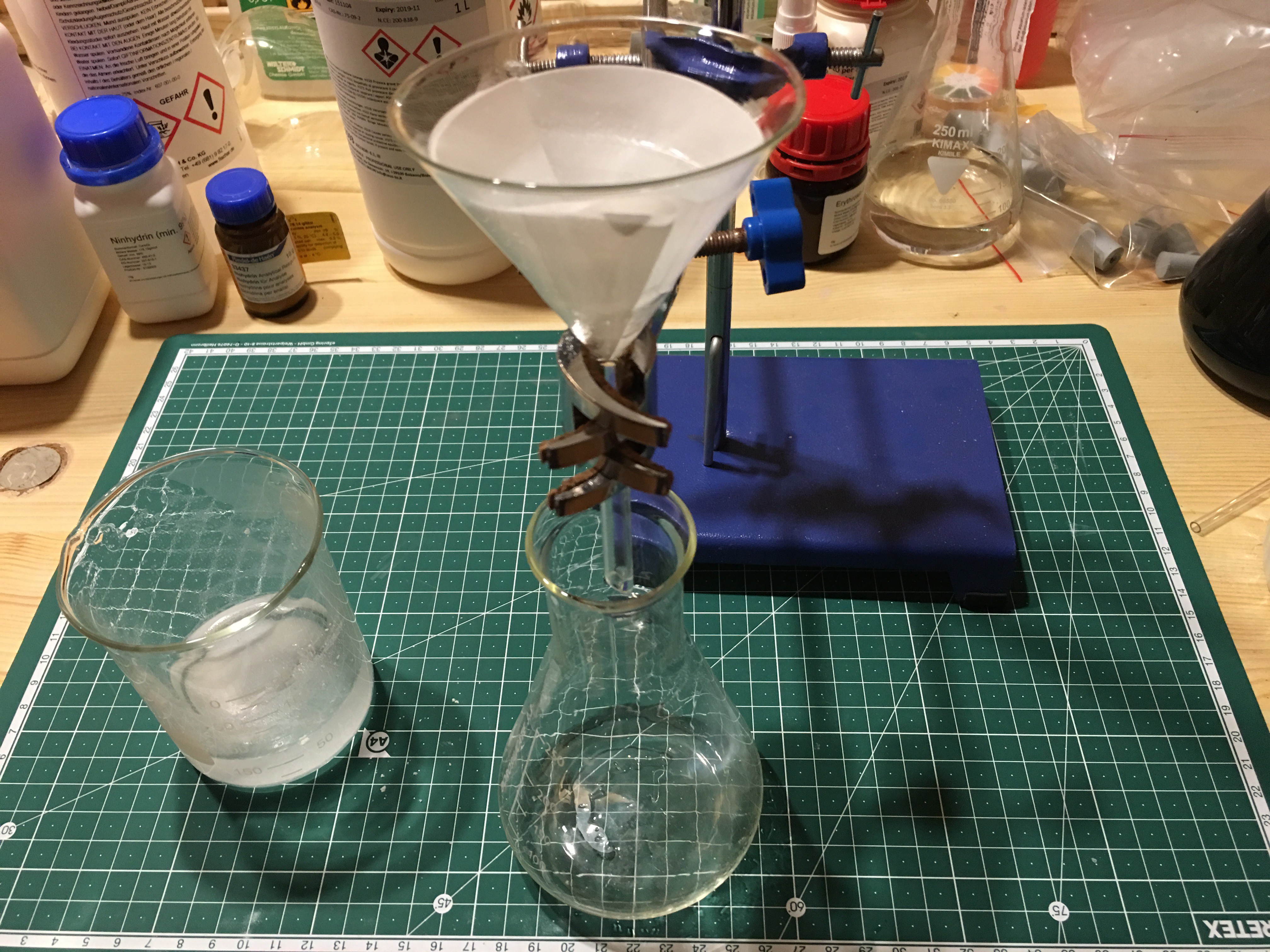 Afterwards I
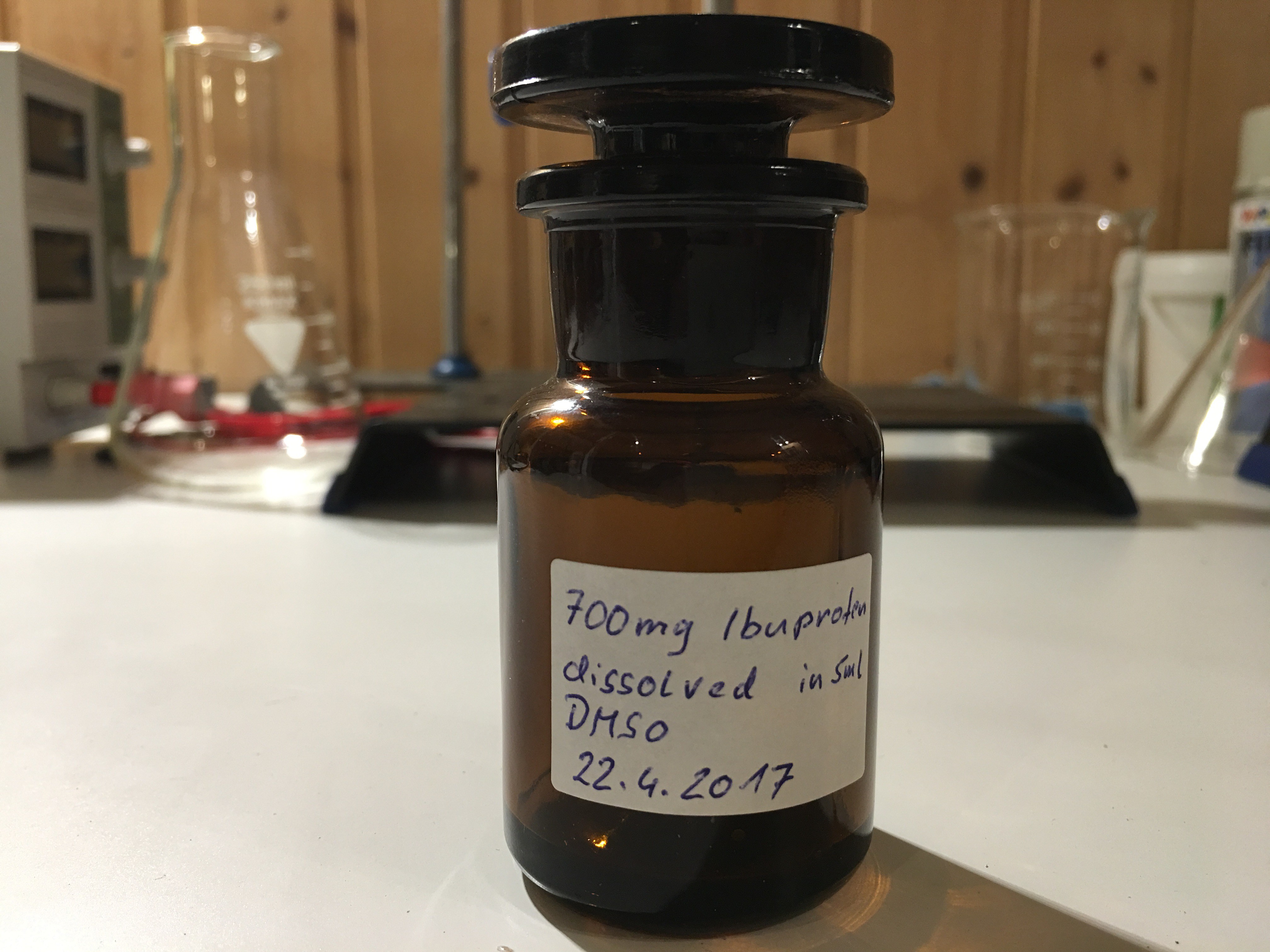
 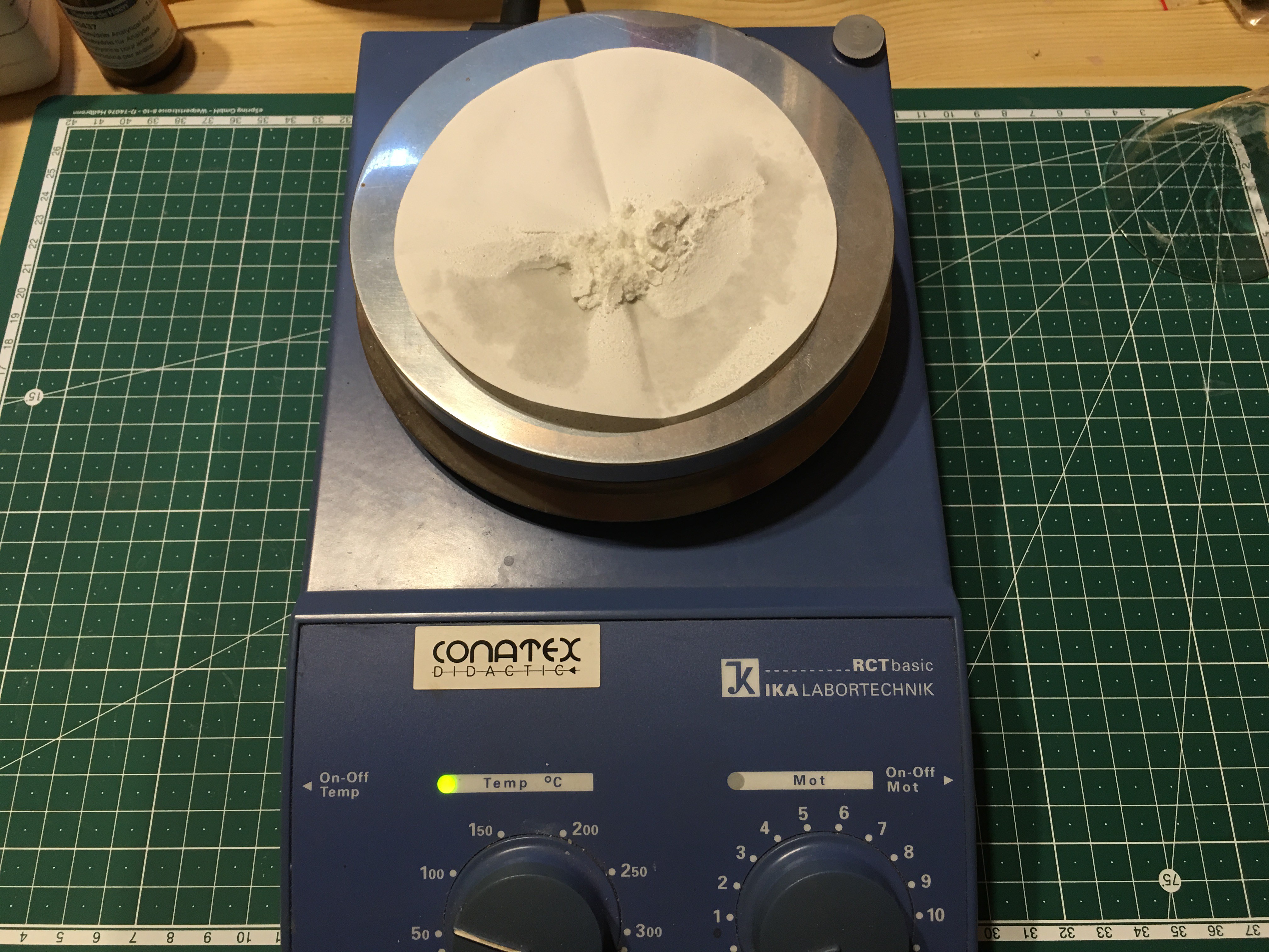 Next I dissolved
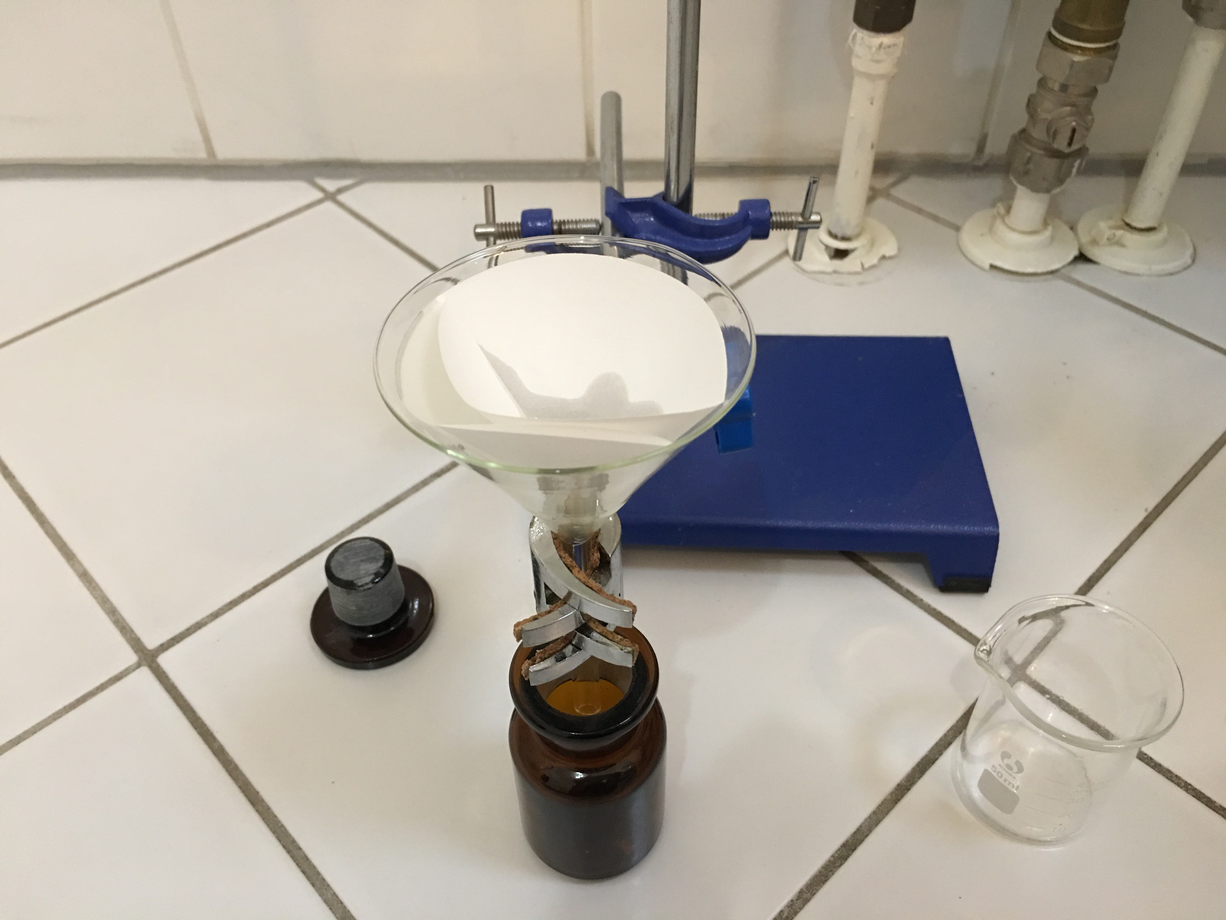
 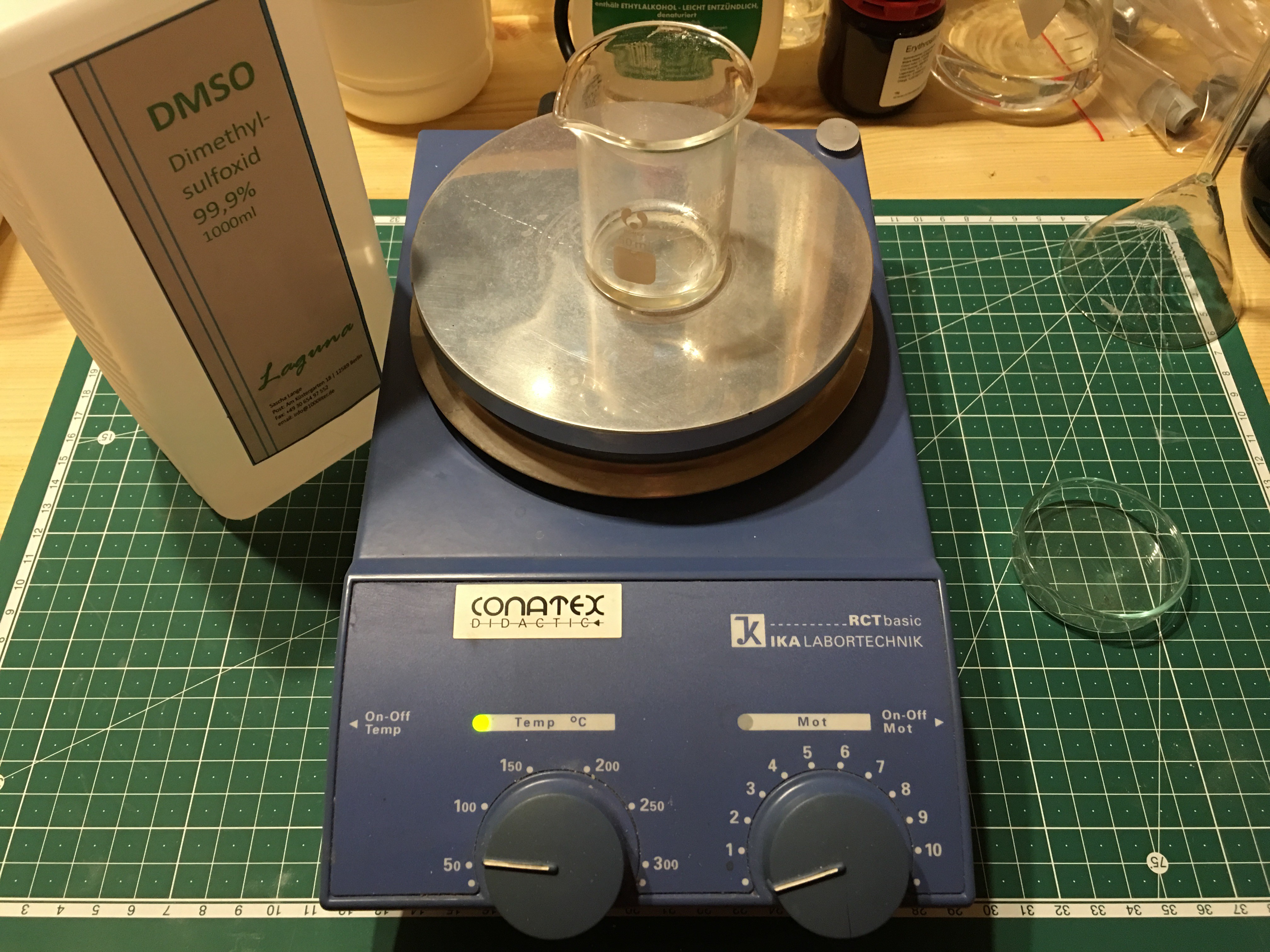 Then I filtered the solution again off directly into a brown medicine bottle. I used a quite warm place (nearby the radiator in my bathroom with floor heating; melting point of pure DMSO is approx.
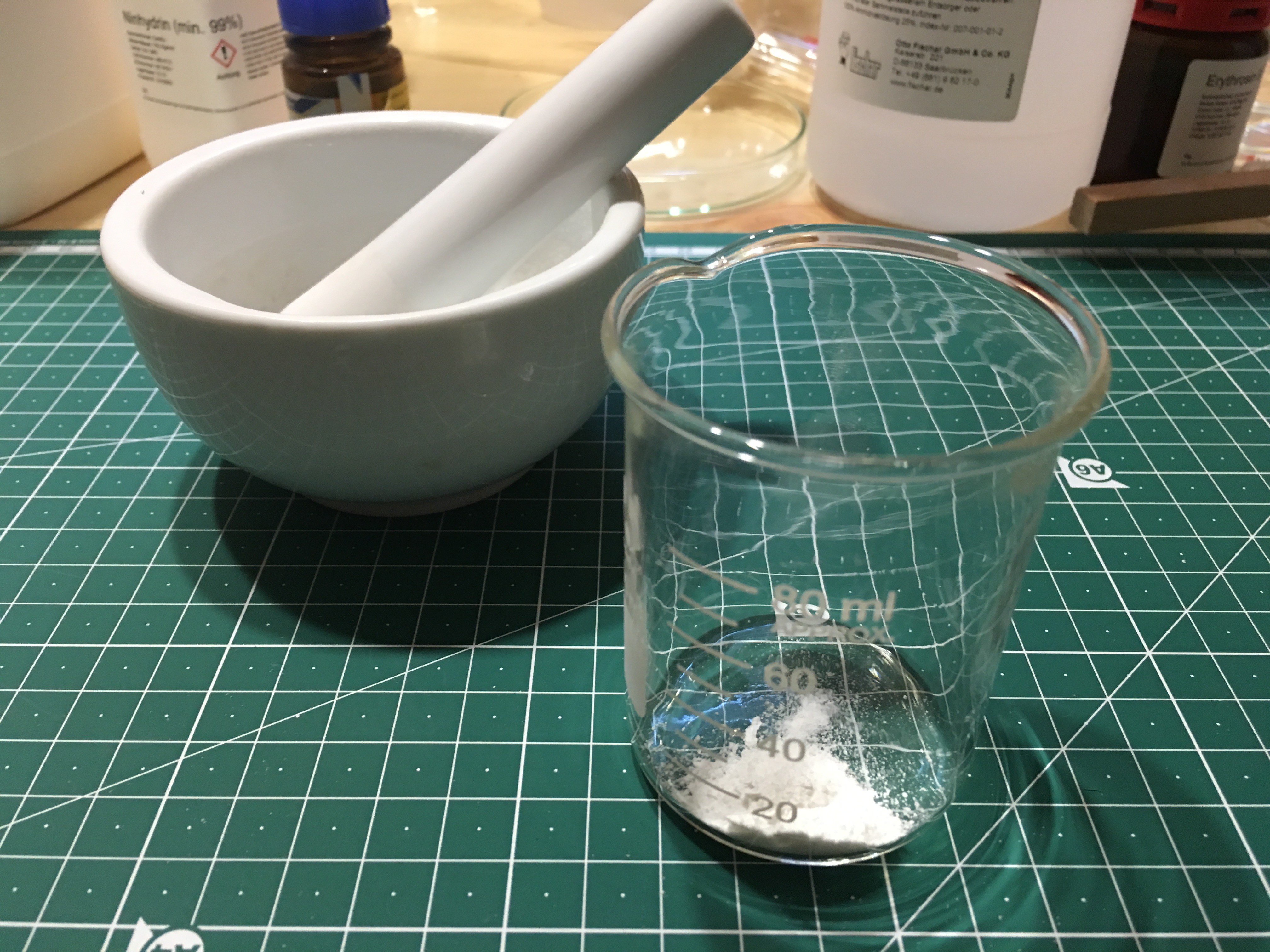
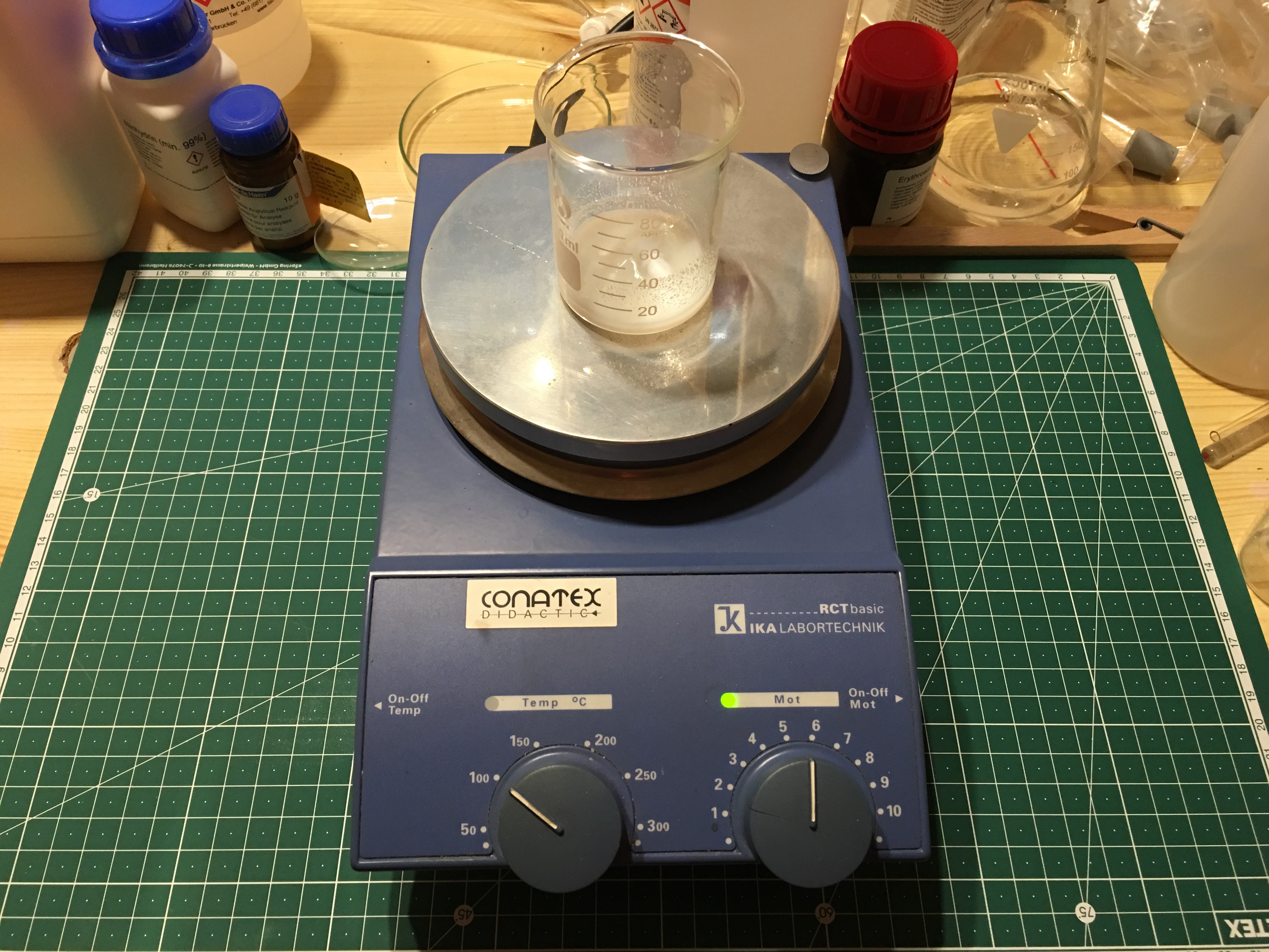
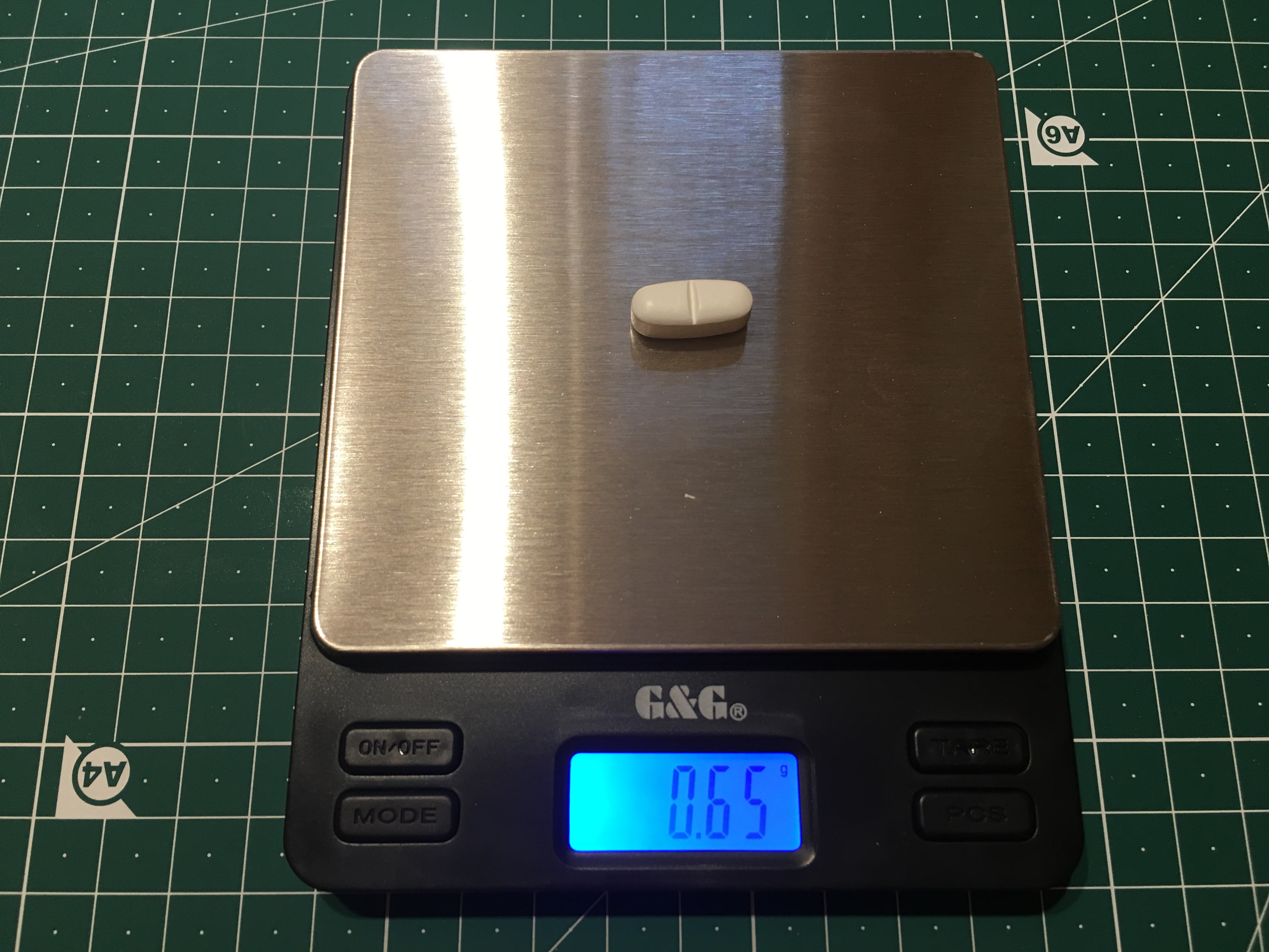 I pestled the pill and added 10 ml warm pure ethanol to dissolve



You are doing a wonderful job here I am also working on a philips epilator blog you can see here its also a very new ide.