 deʃhipu
I made the trip to the hackerspace and used their hot air gun, and desoldered/resoldered the chip properly. I can now confirm that the resistors that I removed from the example schematic in the datasheet when designing that version of the PCB were in fact necessary for the chip to function. Who would have thought! Oh well, I just need to wait for the other version of the PCB, with all the resistors, to arrive.
In other news, I also received the PCB for the 7x11 matrix and the IS31FL3736 chip. Unfortunately, there is a small problem with the QFN footprint that I used (instead of making a custom one based on the datasheet):
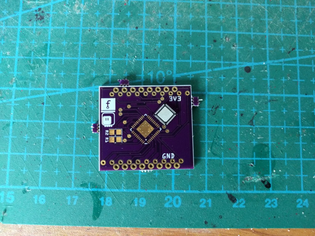
Turns out that just taking a 36-pin QFN footprint and adding the pins to make it a 40-pin QFN footprint is not enough -- you also have to scale it down. I have now corrected all my QFN footprints for those chips to be exactly like in the datasheets, and re-did the PCBs. Of course it's another couple of weeks until they arrive...
Discussions
Become a Hackaday.io Member
Create an account to leave a comment. Already have an account? Log In.
still a bit confused with the matrices I've send you. They should work with the HT16K33, but just not with your HT16K33 shield, right?
Are you sure? yes | no
Yes, I need to design a different PCB for them. However, I was hoping to get them to work with the IS31FL3736, because then you get brightness and breathing control of every pixel individually, which is kinda cool.
Are you sure? yes | no
I'm finalizing a design as well :)
Are you sure? yes | no