deʃhipu
-
Chips!
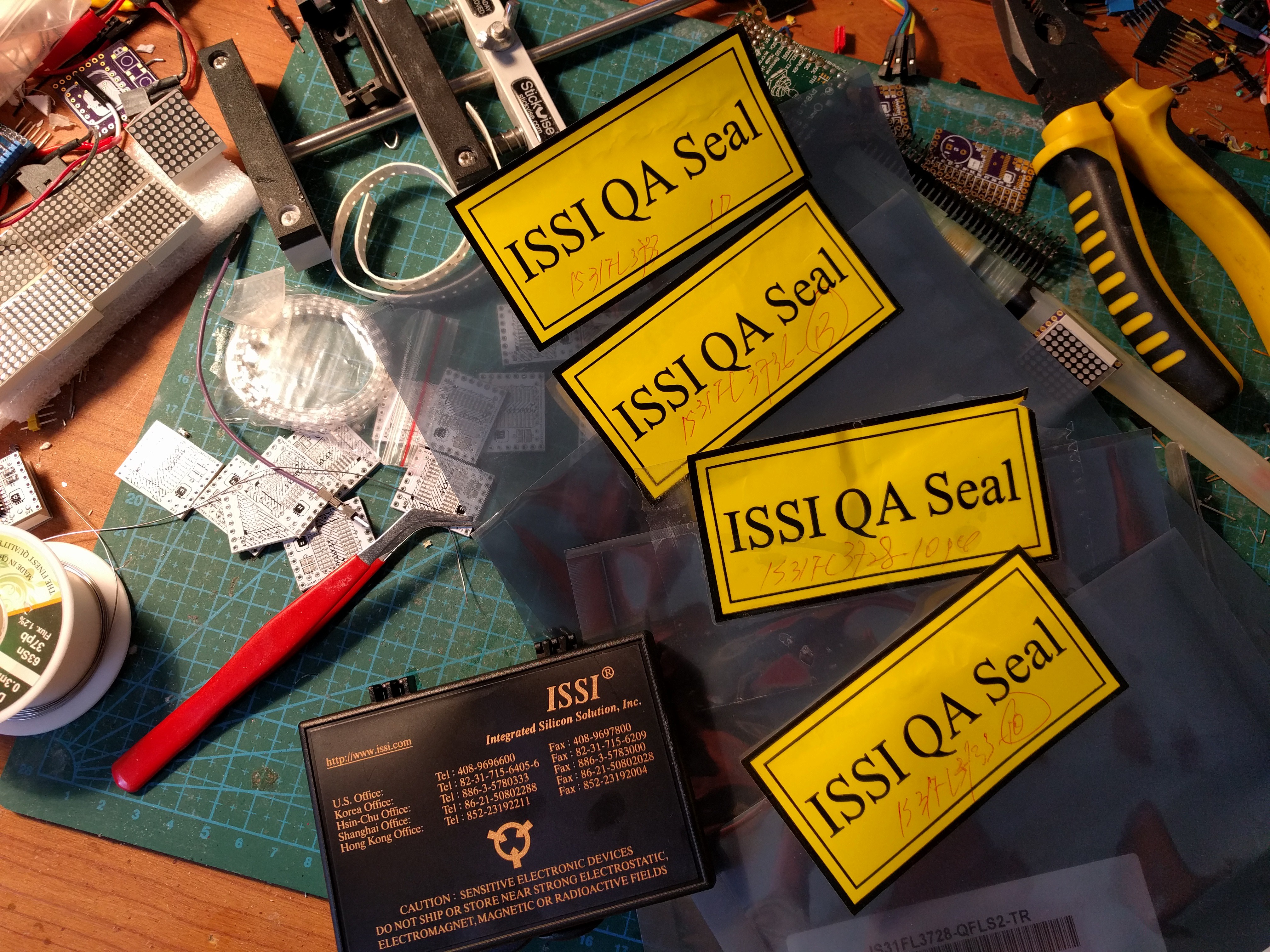
04/10/2017 at 21:23 • 1 commentThe chips arrived today!
![]()
And since I already have the first version of the PCB for the 8x8 matrix, I decided to give it a try, even though that PCB actually misses two important resistors, and instead connects signals directly to VCC/GND. So I first tinned both the pads and the chip:
![]()
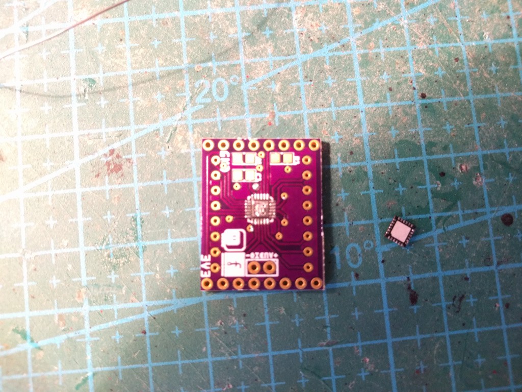
I wasn't supposed to tin the center pad, but a bit of solder got there, so I spread it as thinly as I could. Next, I placed the chip as precisely as I could, and heated the pads with my soldering iron, one by one, until the solder stuck to the sides of the chip. Added flux and removed excess solder. Ready!
Except the connections weren't very good. I had to re-touch some of the pads, until I got it to appear properly as 0x96 on the I²C scan. But some of the rows still weren't displaying, so I re-touched some more pads and... apparently the solder from the ground pad got onto the VCC pad -- I have a short in there now, and no way to get to it.
Tomorrow I will go to a hackerspace and use their hot air gun to remove the chip and solder it properly.
-
The 8×8 Monochrome Matrix
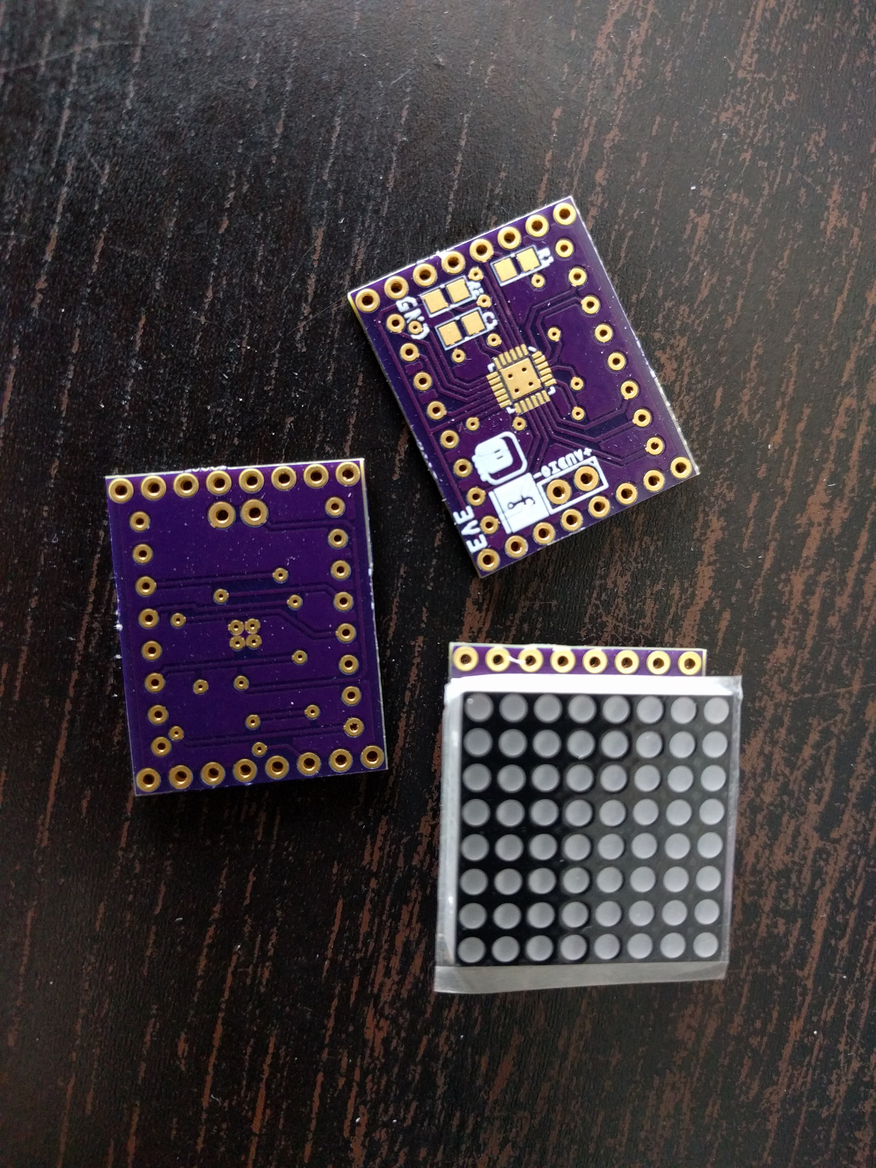
04/08/2017 at 12:43 • 0 commentsThe first shield I'm going to make is a standard 8×8 matrix with red LEDs, using the IS31FL3728 chip. What's the difference from the HT16K33-based one then? Well, not much. It's still "on/off" only for each LED, with a global brightness control. There are two extra features, related to the analog input pin that this chip has: you can modulate the brightness of the whole matrix according to an audio signal, and you can switch it into "equalizer mode" -- not sure what it does then, but you can guess.
I have the PCBs already, and I should get the chips on Monday. I will need to do some tricky QFN package soldering then, but I have a couple of tricks that should work.
![]()
D1 Mini Matrix Deluxe Shields
Shields for the D1 Mini ESP8266 board using the ISSI chips