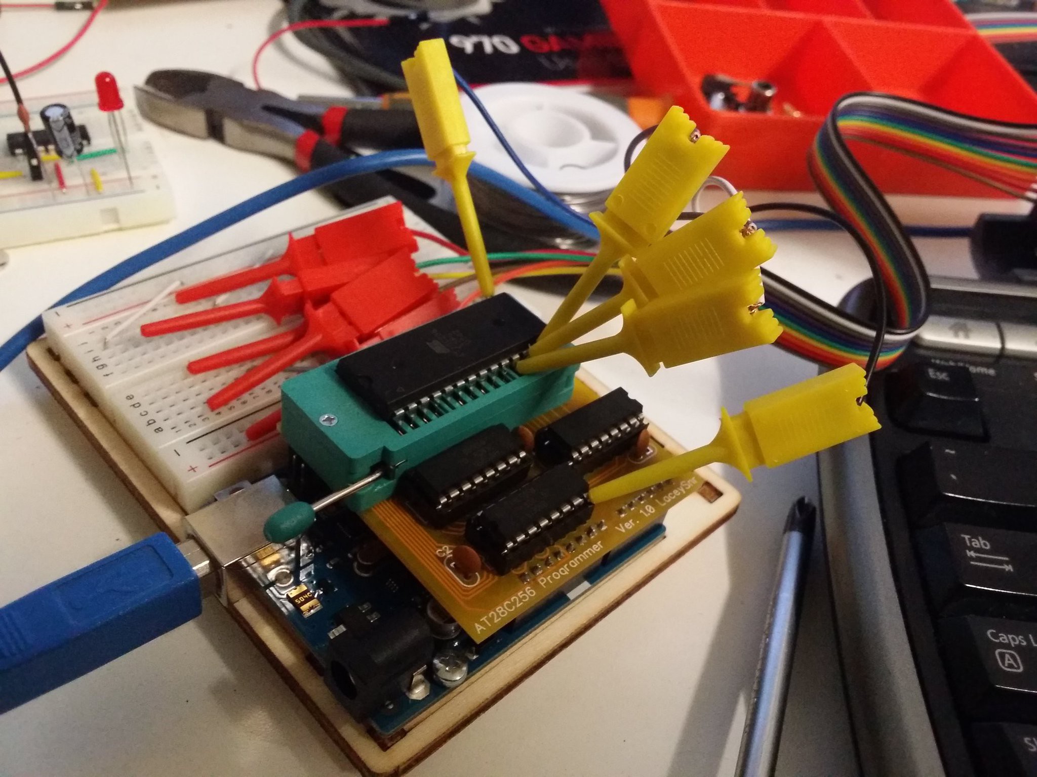
So the EEPROM rabbit hole was a little deeper than I thought, but it was massively valuable in terms of learning for me. Having gotten the EEPROM programmer working on the Arduino, I decided it'd be good to make it more permanent, which meant making a PCB.
Design
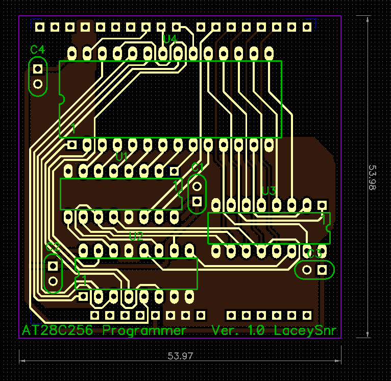
Before this I'd never even designed a PCB so the first steps were finding out about tools to do both a schematic and then a layout. Having played around with all of the big names out there (Eagle and co.) I realised that almost none of these tools have a particularly intuitive UI. The one I found most friendly for all aspects of the design was DipTrace and so that was the one I ended up using, features I particularly liked were the speed at which you could sort out bus lines in the schematic along with the net labelling, and the easy schematic->PCB process. Also for a newbie it made easy work of pattern editing and the like, which I hadn't though I'd need but came in handy for the ZIF socket.
Overall creating the schematic wasn't too hard, though I did miss a few of the control lines at first, making my first two iterations of the PCB routing useless. Having put those in I went through a few more revisions and although the result isn't the best (it'd look prettier with a full fill each side methinks), it does work.
Manufacture and Assembly
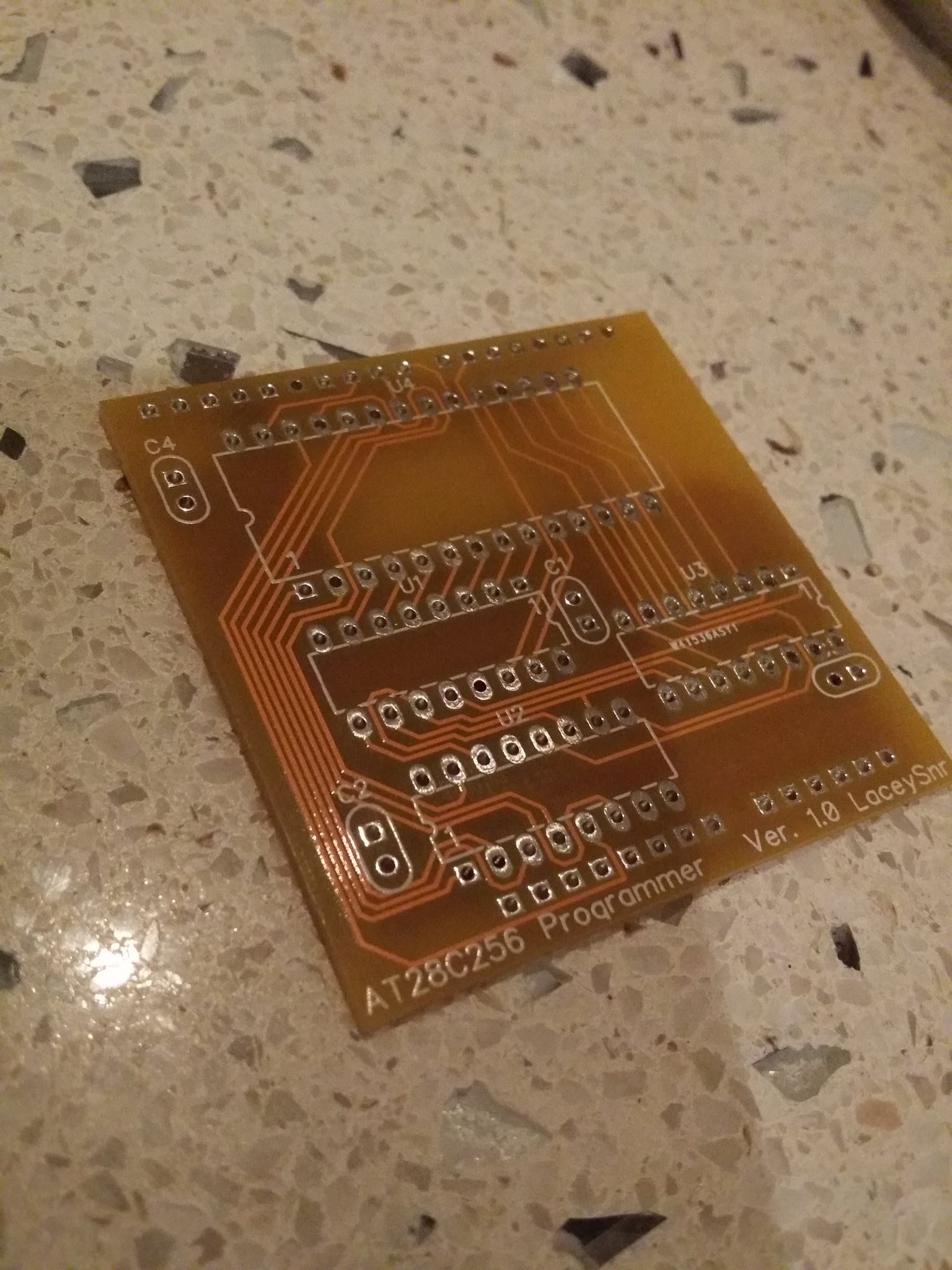
I had the boards made by PCBway and was super happy with them: great price, great speed, and there was some live chat help on hand for a newbie like myself. Receiving the boards was pretty exciting for me as a lifelong software person, though I wasn't convinced they were going to work because in my eagerness I'd completely neglected to check the final routing against my breadboard prototype.

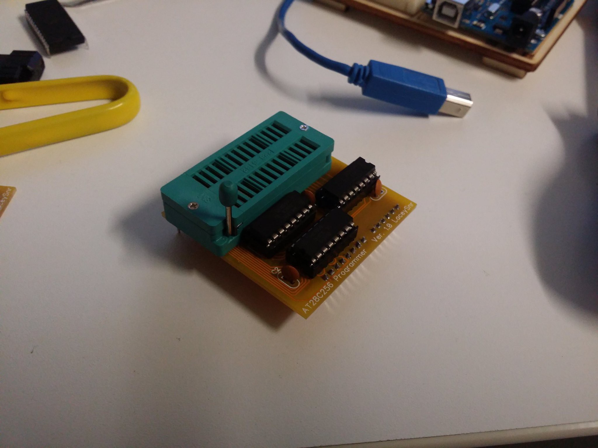
I soldered some sockets onto the board, as well as the pin headers and a few bypass caps, and all in all I'm pretty happy with the result. Not the best soldering I've ever done, but it's the first time I've done a board like this and it was pretty fiddly in places to say the least!

One thing that might be obvious from the above pictures is that I completely underestimated the size of the ZIF socket. I'd not bothered finding a pattern for the silk screen (which would definitely have helped) and instead just printed out the PCB design and eye-balled the width. First off this mean that the socket for U1 is literally against the ZIF socket, it didn't quite stop it going it but it was close, and I thought I'd have to solder the shift register direct to the board. The other thing you may have realised now is that I didn't consider the length of the ZIF socket, I knew it was only a little shorter than the board, but stuffed up in that there's no room to mount the bypass capacitor for it. I didn't fret over this since the original breadboard version only used two caps (at a far greater distance) and worked fine.
Testing
My first test was a little underwhelming in that attaching my logic probe to the data pins of the EEPROM and trying to read it didn't return the data I was expecting. I immediately assumed the worst and figured I'd made a mess of the schematic, but as I poked around some more I saw that some signals were definitely there, and so started going through things one by one. It didn't take long before I remembered that in doing the PCB routing I'd changed the Arduino pin assignments to make the routing easier (it's just a simple software change after all) and I'd not bothered to update the code at the time. Modifying the code to reflect the new layout took a few minutes and then it worked perfectly, making me a happy bunny indeed.

Files to Come
I doubt anybody is interested, but if they are I'll post the design files up soon along with the Arduino code, the latter needs some work to really be usable but it gets the job done. It'll never be able to fill the EEPROM completely as it's dependent on the ROM to write being stored on the Arduino's own controller, which has the same total capacity but with some reserved for the code itself. Still, close enough ;)
 Matt Lacey


Discussions
Become a Hackaday.io Member
Create an account to leave a comment. Already have an account? Log In.