Last time, I explained how a dual 555 timer created frequency signals that changed with capacitance. Now, I'll explain what happens to these signals inside the microprocessor.
The choice of Microprocessor was very limited, because I needed something in a DIP package that could be placed onto a breadboard. In the end, I decided on a PSoC 1. This is an old generation of chip and the development software required me to manually specify how blocks connected, but in the end I learned more about how System on Chips worked.
The images in this post are from the digital and analog wiring diagrams from the PSoC Designer software package.
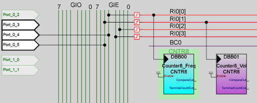
The first step is to read in the frequency signal. I use one 8 bit counter each for volume and pitch. The counter increments every time the input completes a cycle. Every so often, an interrupt reads the counter value and compares it with the previous count. In this way, the processor knows how many times the input has cycled in a given time. By making multiple readings, a 12 bit value proportional to input frequency is generated.
The next step is to calibrate this signal against a baseline, and to filter out any ripples. Also, math is done to correct for the non linear nature of the sensor: sensitivity near the antenna is reduced, and sensitivity away from the antenna is boosted.
How all this happens is the "Secret Sauce" of the project, the one part I wish to keep proprietary. However, if you've read this far, I'm sure you could make similar software if you try. All it takes is a graphing calculator, a basic understanding of feedback and control loops, and a few months of trial and error.
Creating an output from such a small chip was very tricky. I did not have the memory or speed needed to store or use a lookup table with output a predefined waveform. Instead, I broke the output into three stages: Frequency, Volume, and Filtering.
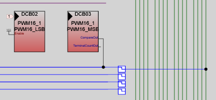
The frequency generating block is shown above. A 16 bit PWM block creates the desired output musical pitch, from C3 to C6 and everything in between. And I do mean everything: the module can create more than 53000 discrete frequencies between the low and high limit (the rest of the 16 bit range is lost on each end).
The output of the PWM module is routed to one of the I/O buses.

	/*Turn On Analog Modulator and set to Global_Out_Even_0 bus*/
	AMD_CR0 = 0x02;
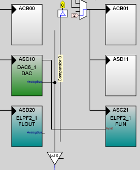
The output of the I/O line modulates the ASC10 analog module. Now, the output of the analog module will change flip between positive and negative at the same frequency as the PWM module. Note that the reference of the analog modules is 1/2 VDD, or 2.5V. The signal will be flipped across the reference voltage: 0V to 5V, or 1.5V to 3.5V, or 2.5V to itself.
I created a DAC at this analog block. When this 8 bit DAC has a value of 31, the signal will be at exactly the reference voltage. Flipping the signal just returns the same reference voltage. Thus, at a value of 31, the amplitude of the signal is zero. As the value of the DAC goes lower and lower, the amplitude of the modulated signal increases. A value of 0 creates max volume.
So, the PWM creates a frequency that modulates a DAC. And changing this DAC changes the amplitude of the signal. But the creates a harsh square wave with plenty of harmonics. To create something pleasing to the ear, an analog filter is created inside the PSoC.
Thanks to the magic of Switched Capacitor circuits, I create a low pass Buttersworth filter using the analog blocks ASD20 and ASC21. After filtering, the tone is softer, closer to a sawtooth.
The output signal is sent out to an IO pin and connects to one side of a magnetic speaker. The PSoC can sink twice as much current as it can source, so the other side of the speaker connects to VDD.
So, that's how the microprocessor (and assorted digital and analog blocks) turn a ~800 kHz and ~500 kHz signal into pitch and volume. But there's more going on.
Up next, I'll explain the design and firmware decisions I took, to account for beginner mistakes and to teach the troubleshooting process.
 David Levi

Discussions
Become a Hackaday.io Member
Create an account to leave a comment. Already have an account? Log In.
interesting, thanks.
Are you sure? yes | no