 morph
morph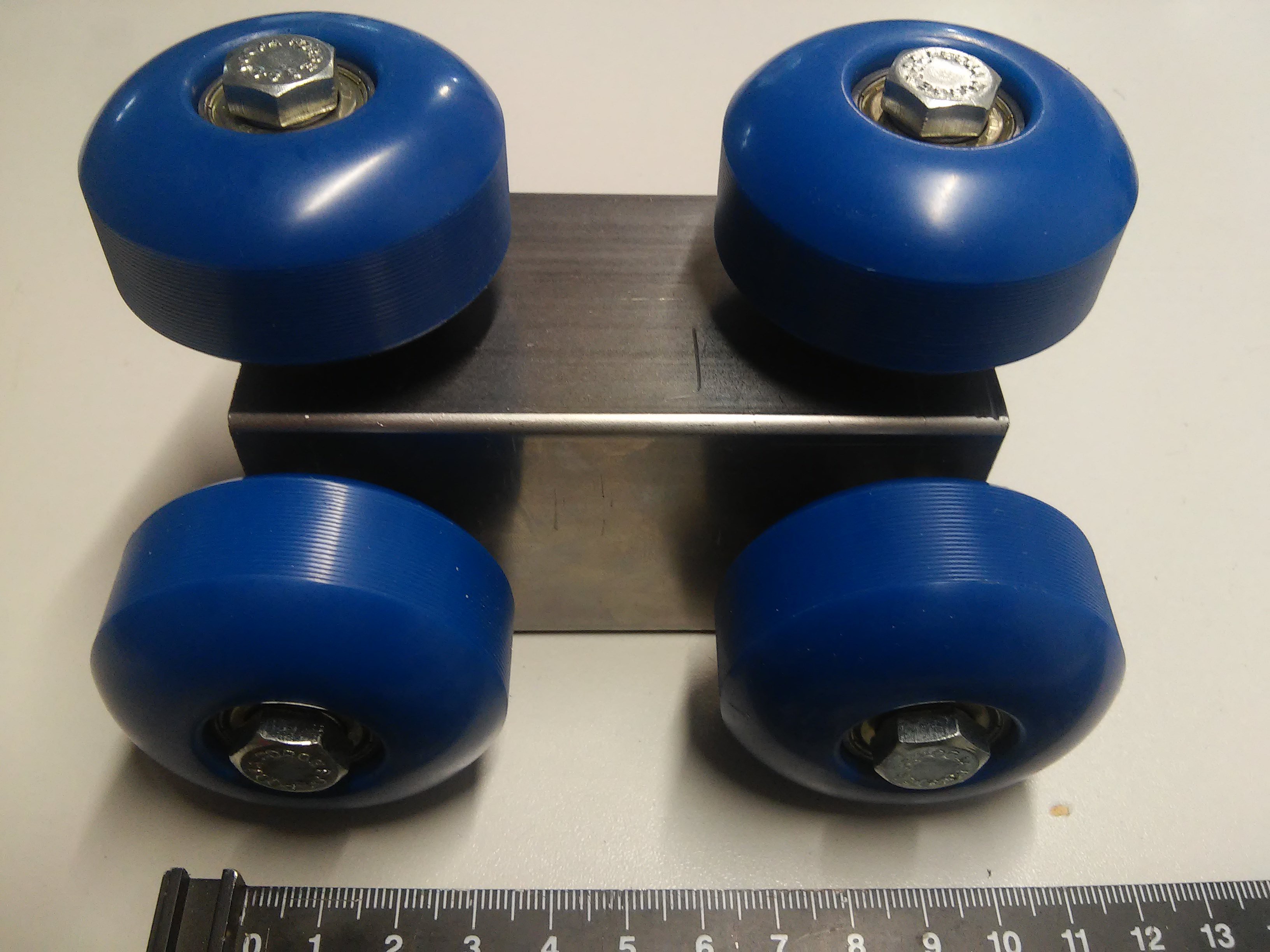
After staring at the 20cm carriages that I had sawed off from the 50x50mm pipe, I decided to split them to make 10cm long pieces.
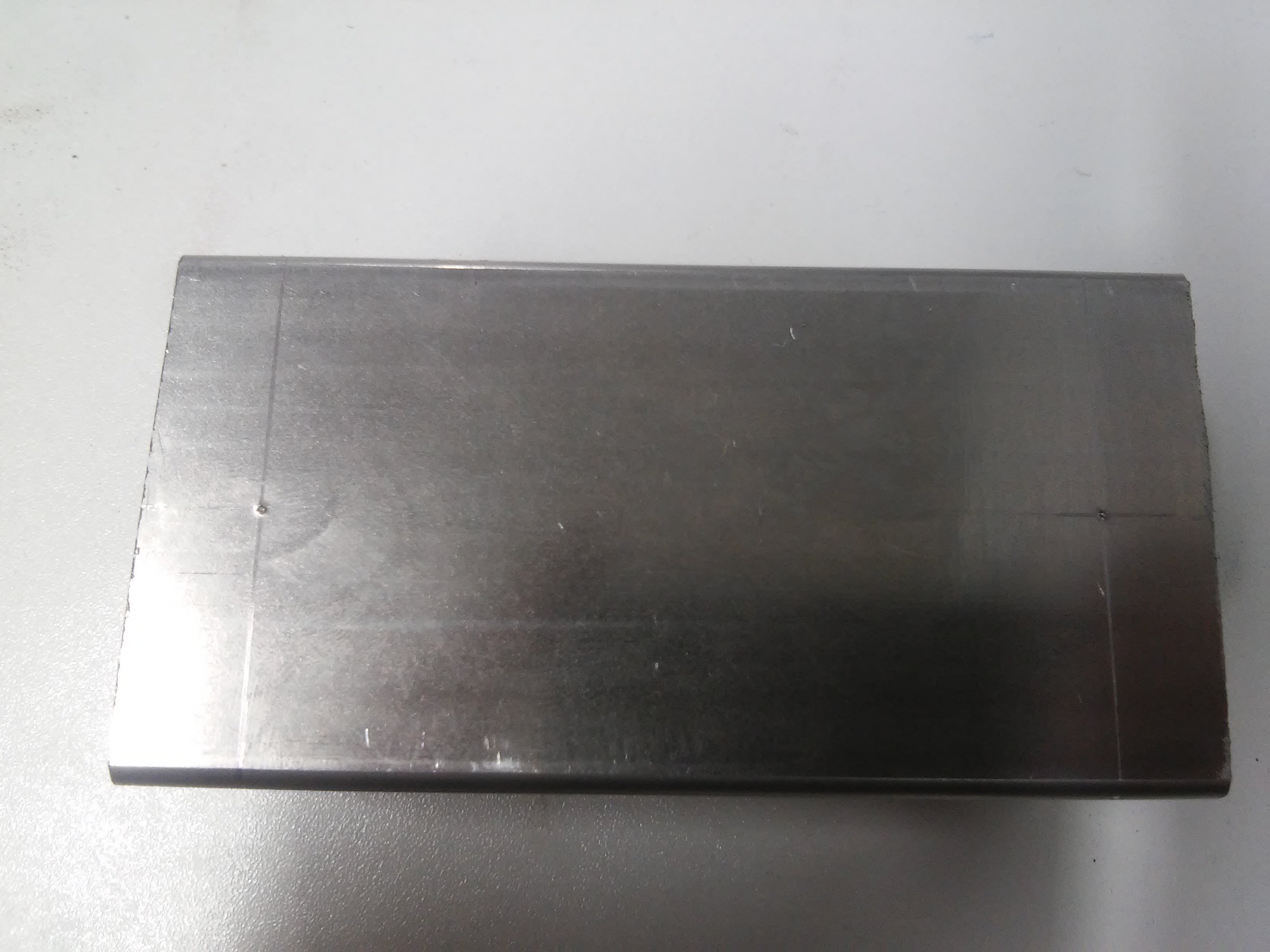
Each wheel attachment hole is approximately one cm from the edge. The holes should be precisely centered in the vertical axis.
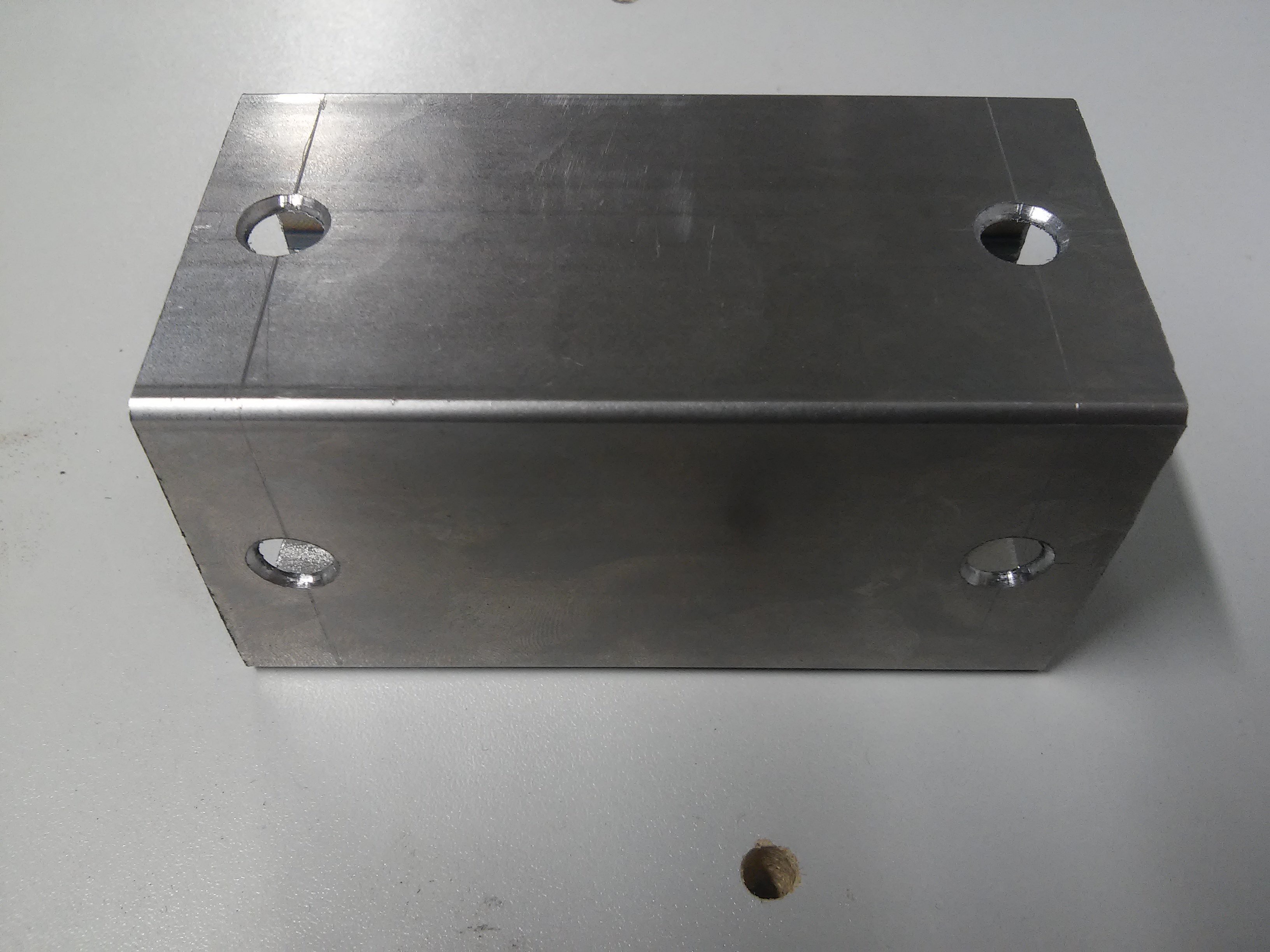
First a mark was punched by hitting a nail with a hammer at the intersection of the scribed lines. Then a small guide hole was drilled with a 3 mm drill bit. Finally it was brought to approximately 8 mm with a step drill. The step drill is a very good tool to get nice round holes without a drill press. The wheels spin nicely when the nuts are a little loose. However I forgot that I need bearing spacers inside the wheel so I ordered those, they should stabilize the wheels and eliminate any wiggle. I'm also ready to expand my 8 mm holes to 10 mm to allow for adjustment when the machine is put together, let's see what happens.
Discussions
Become a Hackaday.io Member
Create an account to leave a comment. Already have an account? Log In.