 Dr. Cockroach
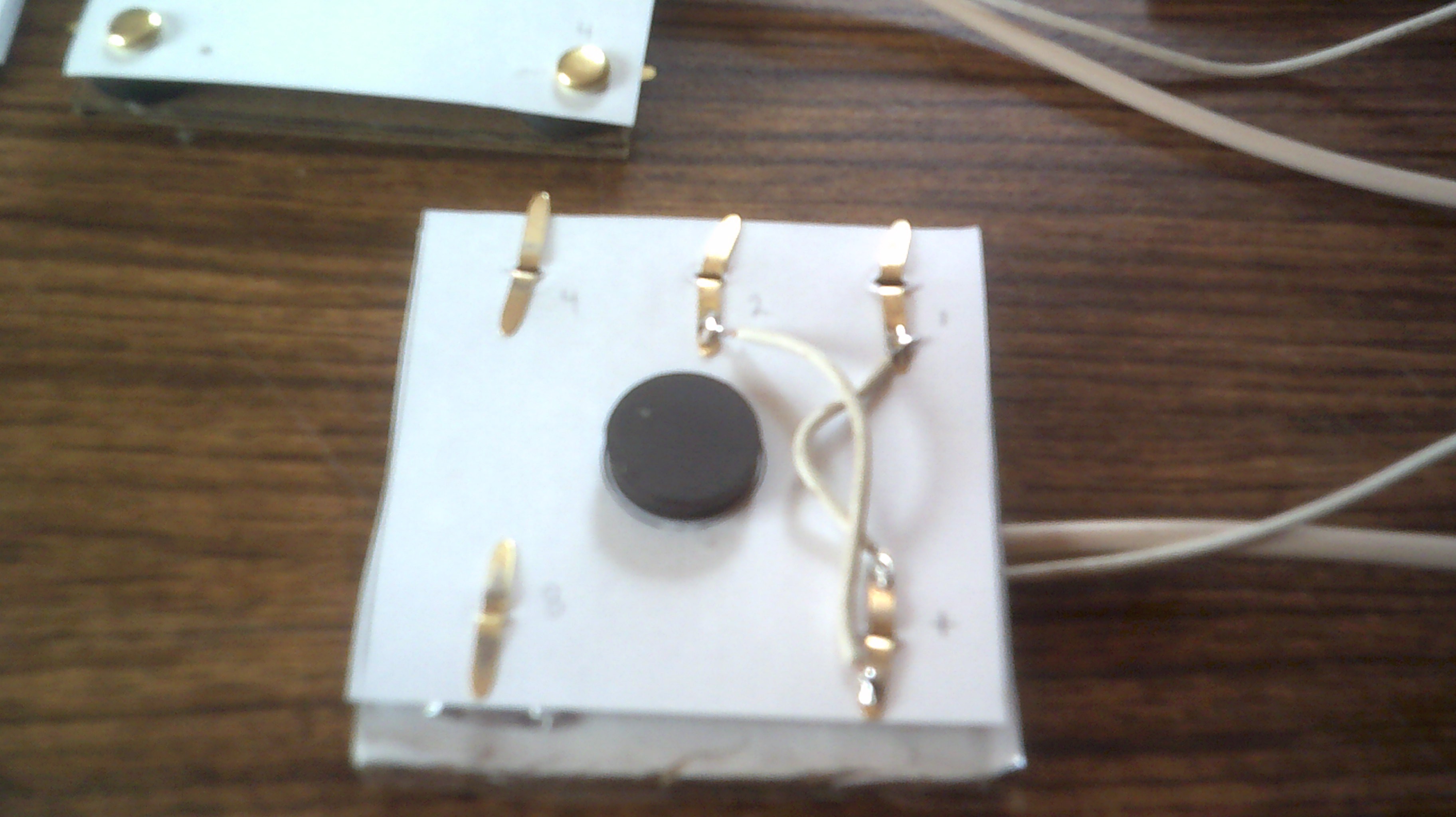
I was using some very weak magnets from the local big box store to provide the holding power needed to keep the card is contact with the reader pad. The first version was not making anywhere near 100 percent correct contact and it was decided to rearrange the contacts and use one set of central magnets. I found some ceramic magnets that provide the holding pressure needed and with the new contact layout, I now have a 100 percent correct contact rate. The photos below illustrate how the card and pad are constructed.
The foil pads are kept in place using the brass fastener tabs as hooks. The wiring is simple enough. One contact is +5 volts and the other contacts are the binary outputs to the test leds in this case. The magnet for the reader pad is hot glued to the bottom and in the center
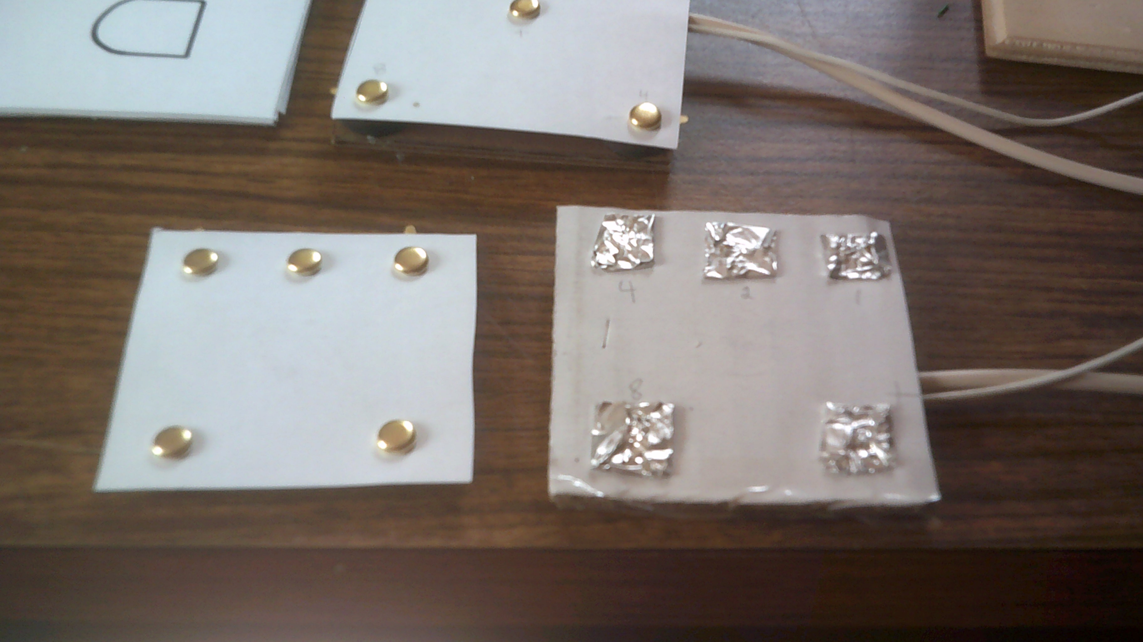
When the instruction card is placed onto the reader pad, the magnets hold the card in place and the brass contacts make solid contact with the foil pads. A cover with the needed graphics will be added to the instruction card.
Discussions
Become a Hackaday.io Member
Create an account to leave a comment. Already have an account? Log In.