 Vijay
VijayIts time to put it all Together! I will posting a better "how-to" in the instructions section after the project is done. I will be just covering instructions on assembly here.
Assembly:
1) Silicone button pads
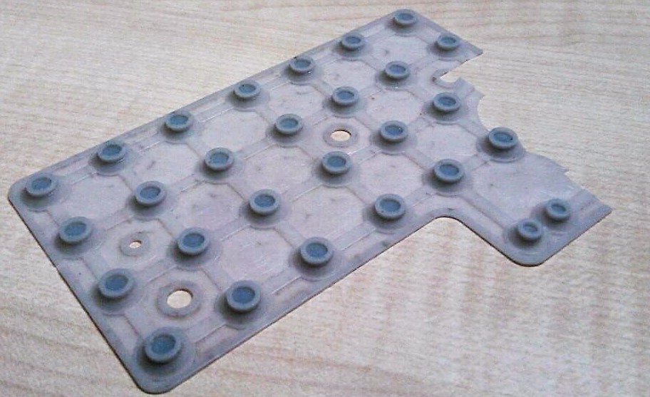
The parts I ordered from Ali-express didn't arrive on time, so i had to resort to desperate measures. I broke open a calculator, and salvages its button pads.
2) Cutting and alignment:
I cut the silicone pads into small section to git on to the small form factor, and not come in between some of the passive electronics on the PCB.
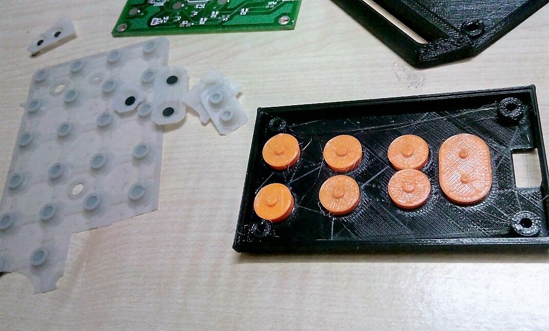
The buttons have projects on them that align with depressions on the silicone pads. In case you have a different SKU of silicone button pads, you might need to change the CAD files of the buttons I have uploaded for best results.
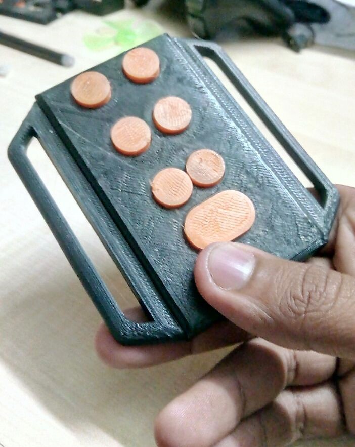
3)Closing Up
The PCB should align along with the pads, thanks to my mastery in CAD ;P
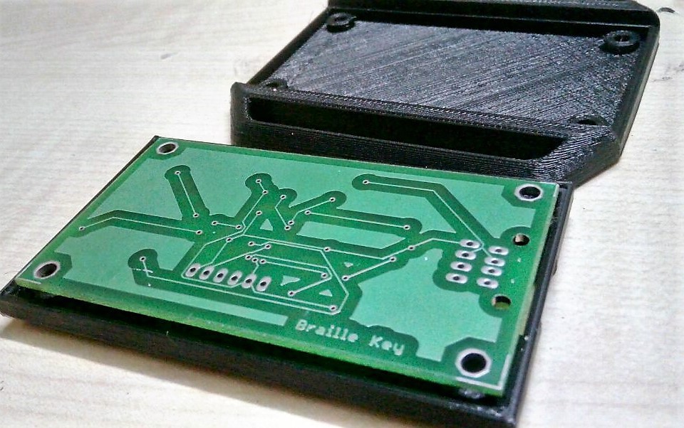
Close the other half of the clamp-shell.
Discussions
Become a Hackaday.io Member
Create an account to leave a comment. Already have an account? Log In.