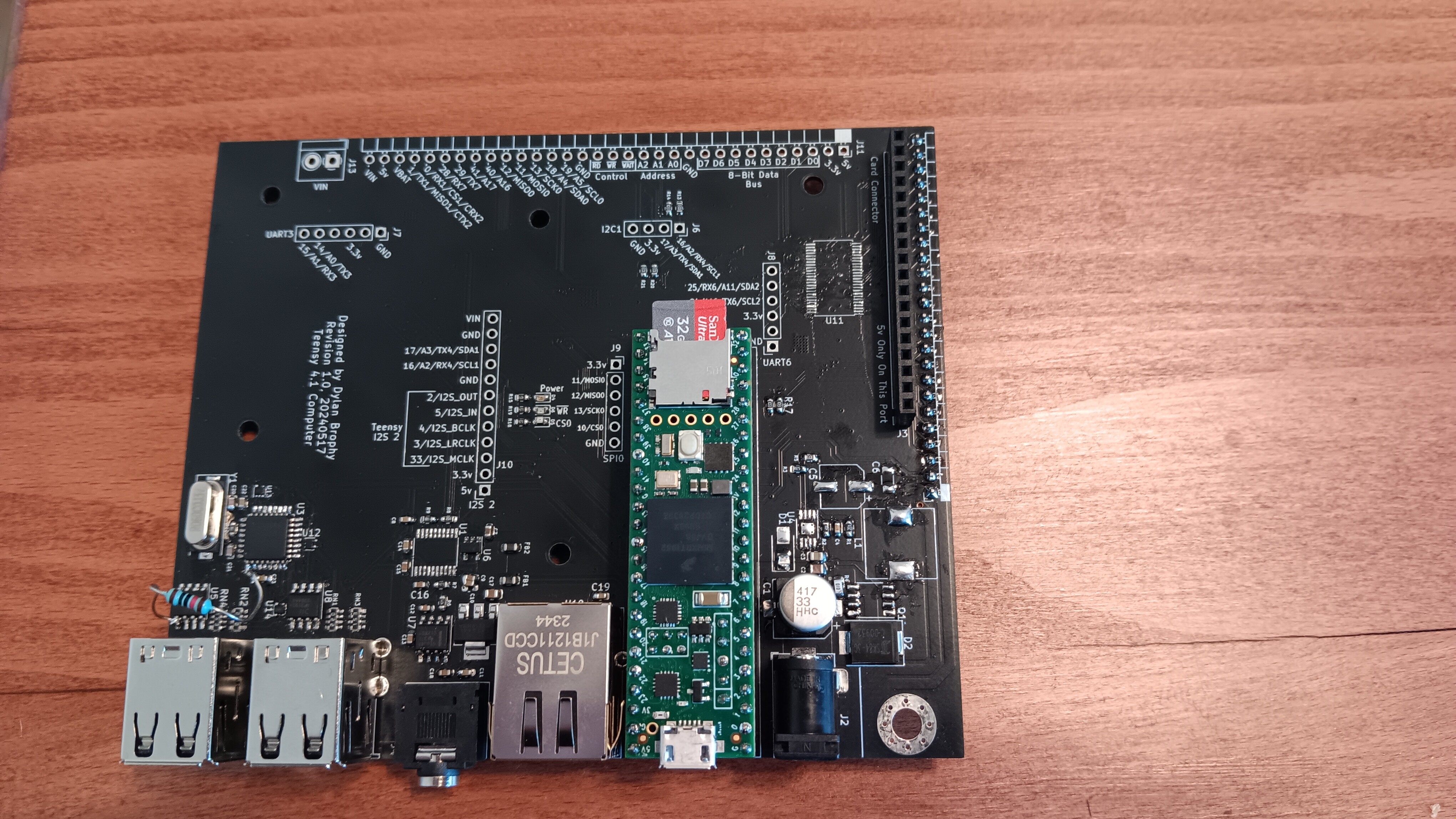
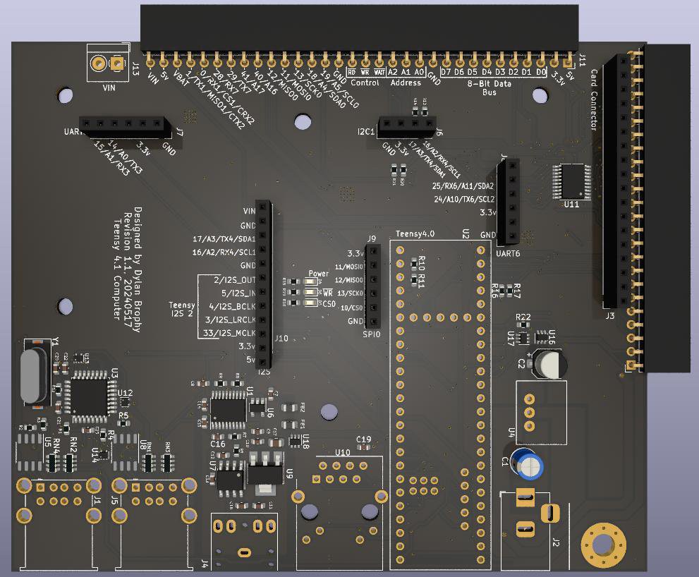
Last log I designed a board and ordered it; a few days ago I received that board and assembled it. Here's what it currently looks like, after some alterations:

The board came out nice if you ignore the modifications. Unfortunately, after I baked the board for SMD soldering, the board fell while the solder was still liquid and components got thrown off the board. When I put them back on, I mixed up two of the ICs, and I think this is why the voltage regulator flooded the 5v line with 11v. Needless to say, numerous components were destroyed, so I don't know if certain components work. Nonetheless, I was able to find several issues with my design, and so I'll be doing one more board run with a few modifications:
 List of changes:
- Added ideal diodes to control flow of power, to prevent regulator backfeeding and to control power going to the audio amp
- Added missing pullup resistors to the USB hub for overcurrent detection and USB connection detect
- Changed the IC used for 5v level shifting to the 74LVC245
- Removed the buck regulator I designed and replaced it with a "linear regulator replacement". The ones like this I've used before worked great. This one is rated for 2A.
While I wait for the new board to arrive, I've been working on connecting this to my #uPD7220 Retro Graphics Card (and VGA hack), and at this point I can communicate with that card. Due to hardware bugs and fried components, I can only do this by means of more modifications:
The card also has some design bugs, so I had to make some hacks there too. I'll post a log to that project once I get a valid signal from the card - I think I'm getting close.
Well, that is all for now.
 Dylan Brophy
Discussions
Become a Hackaday.io Member
Create an account to leave a comment. Already have an account? Log In.