 Fred Fourie
There has been considerable progress in this project. This is mainly because I have been asking for help (who knew).
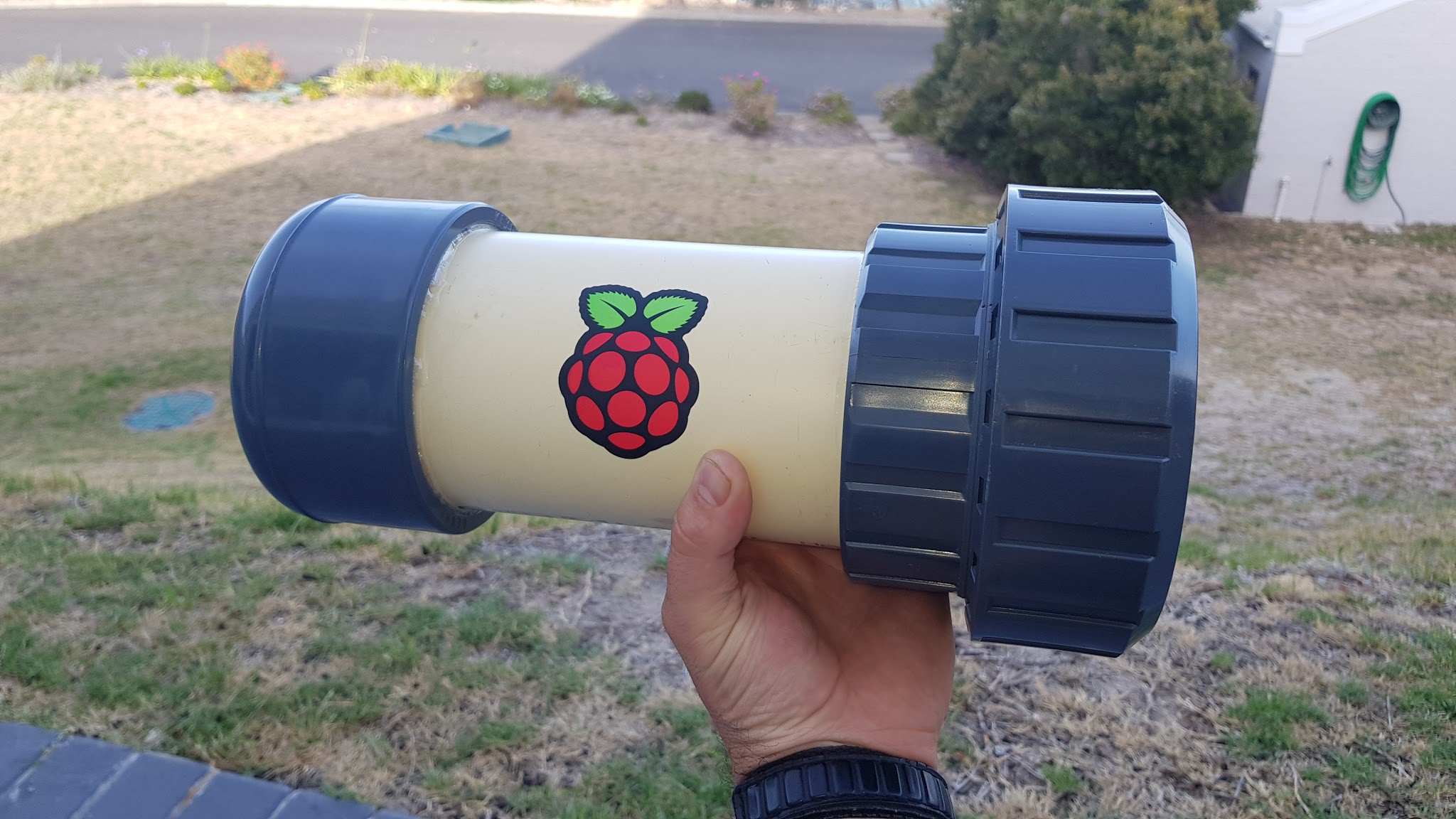
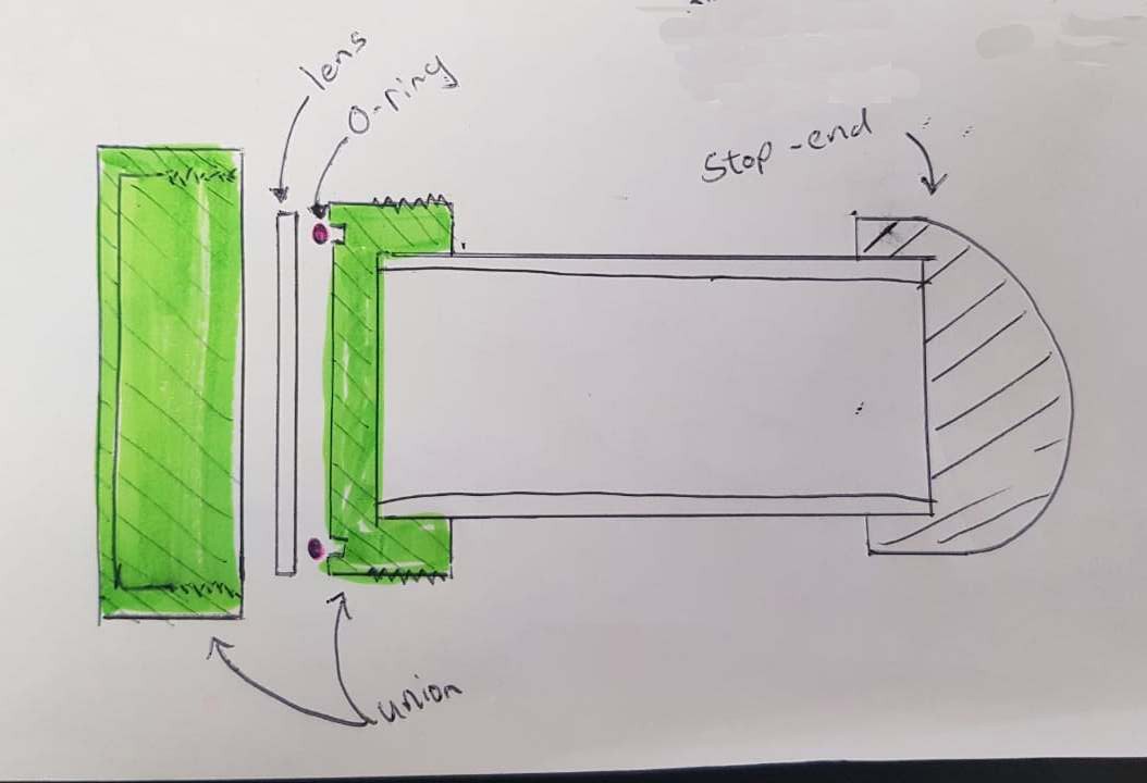
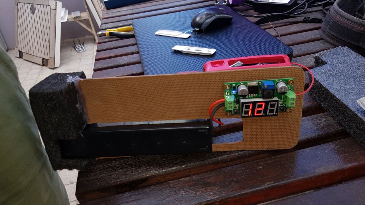
The new housing allows for a great seal and easy access to the electronics. The key to the progress has been the PVC union used to hold the lens and letting go of the tethered idea.
The pipe used is still the 110mm waste pipe, but the new heavy duty fittings has given me the confidence that this project will perform the way mechanically as I hoped.
Summary of what has changed since the last log
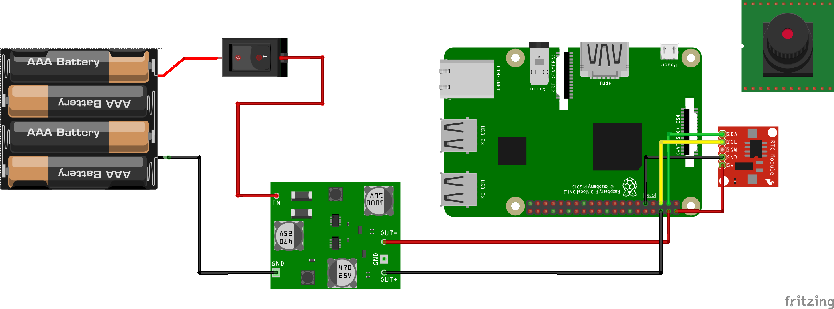
- Now using a Pi3 instead of a Pi2
- Camera module is now the PiCam v2
- Raspberry Pi sticker on the tube- totally worth the R15
- Real Time Clock added to keep time for timelapse intervals
- Unit is now self contained and runs off a battery (making a gland brings up issues)
- Lens is now 10mm perspex
- Voltage regulator is now a proper DC-DC adjustable Voltage regulator module
- ON/OFF switch
The parts (costs in South African Rands)
- 110mm Waste pipe (ordering 1m transparent PVC 110mm pipe at a specialist plastics place costs about R300)
- 110mm PVC Female stop end (CA1) (costs about R50)
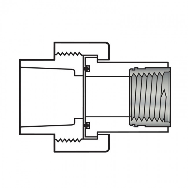
- 110mm PVC union (comes with an oring groove and oring) (costs about R160)
- 10mm Perspex lens (costs about R80)
- Raspberry Pi3
- Raspberry Pi camera module V2
- 12V, 2.4 Ah Rechargable sealed lead acid battery
- Adjustable Dc-Dc voltage regulator
- DS1307 RTC module
- ON/OFF switch
Testing
I approached a friend for help. I gave him the housing and within and hour he had it rigged up and was pressure testing the housing.
These tests revealed a few things:
1. The housing- as is does not leak.
2. The housing could hold 2bar of pressue
3. The 5mm perspex lens leaked when pushed beyond 2bar
4. A 10mm lens was cut, it held 4 bar no problem.
4 bar is good enough for what I need.
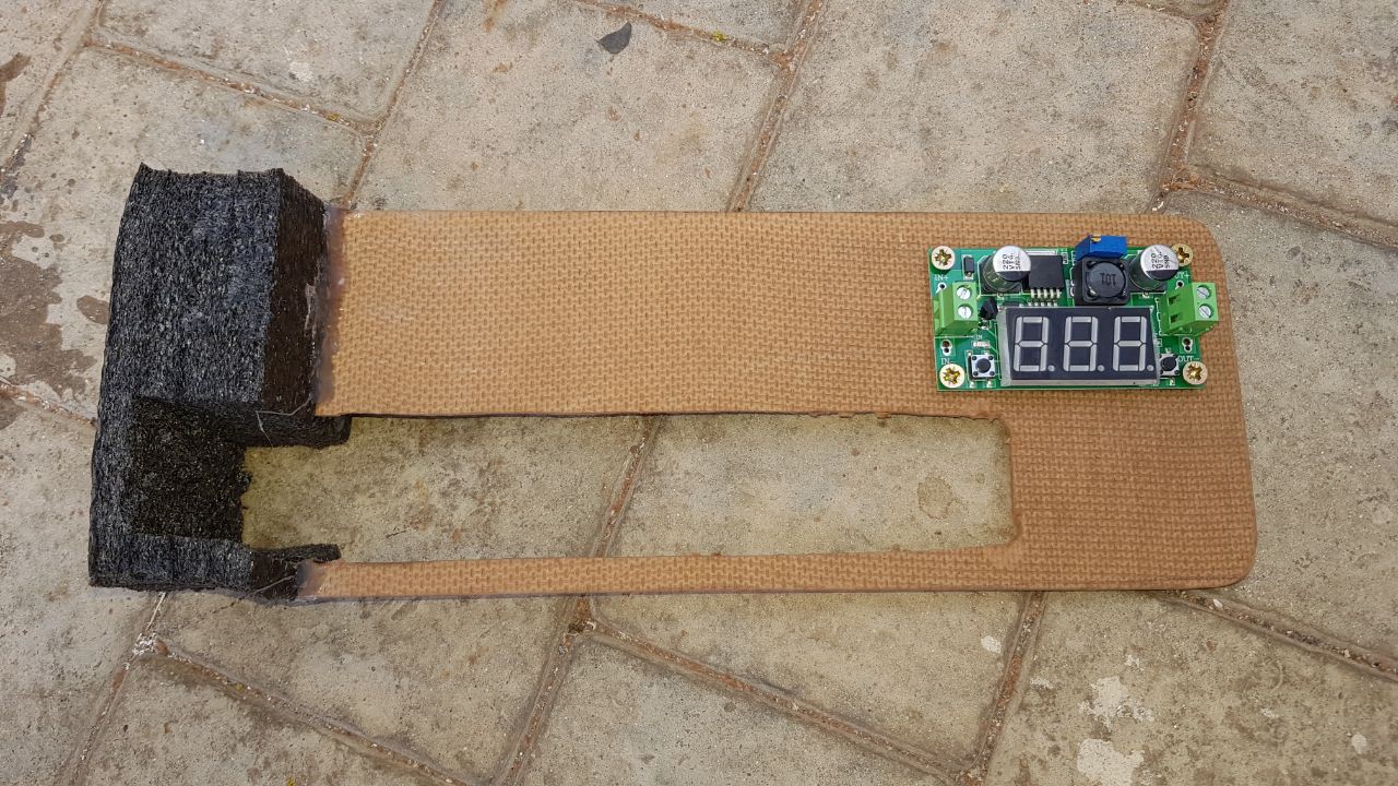
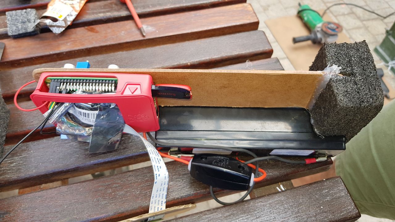
Internals
From my last field test I learned that I need to pay more attention to the internal mountings of the units.
Software
Here is some of the work I've done on the software side to get the project to alpha testing:
- Made USB drive automount
- Installed the I2C RTC
- Installed apache2 - to have a health webpage
- Wrote a python script that does the following:
- Get the date and time
- Takes a photo using raspistill command (picam has been producing poor photos- will investigate later)
- save the photo to the USB drive if it is present and name it the timestamp
- save the photo locally if the USB drive is NOT present
- check the available space on the disks
- count the number of files
- write health status to a json file
- Add script to crontab
Here are two photos to compare a raspistill and python-picam photo:
Default photo taken from python-picam:
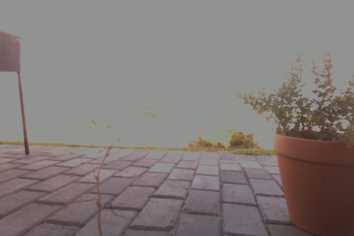
Photo taken using the raspistill command (exposure mode set to 'beach')
Moving forward
It's already obvious that there is a need for more power and better power management. A slightly longer housing will suit more batteries better.
Internal mountings should NOT be overlooked as easy. I will consider a small distribution board to tidy up the wiring and mount the RTC in a sensible way. The current internal cradle is made from hardboard, but a plastic or perspex one would be nice.
For power management I would include a Arduino via I2C to the raspberry pi to give current and voltage reading from the battery. The Arduino could then control the interval of switching the Raspi ON/OFF. The Arduino can also sport an LDR to only switch pi if the light levels are sufficient.
On the software I would make a simple web page displaying the following diagnostics:
- Power levels
- Disk usuage
- Latest photo
Software also need to be able to handle low power states and full disk events
Current Testing
The pipecam is ready for a set of Alpha tests. I had to stop myself from throwing it in the water straight away. The dry test will help correct the photography and get an idea of the system endurance. Minimum endurance should be +2hours (or anything better than a GoPro). The estimation on theoretical values has the endurance at around ~5hours. Test is set to take a photo every 5mins- which is what I believe I would be using for the first set of water tests as well.
Discussions
Become a Hackaday.io Member
Create an account to leave a comment. Already have an account? Log In.