 Fred Fourie
Here follows a quick review of the PCBs/Electronics I have used for the project up to now. The versioning follows a loose numbering conventions, but major versions get a fish name in alphabetical order.
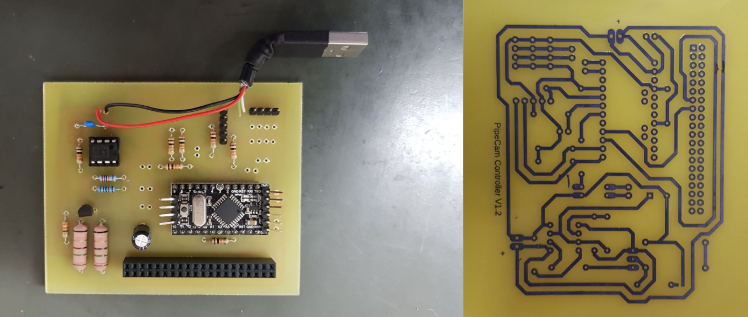
Version 0
Home etched PCB, ran off a power bank that needed a current draw to stay active. Current draw was generated with a dummy load on a 555 timer to keep the power bank alive. Home PCB etching is extremely satisfying, although the rise of the Chinese PCB manufacturer for the hobbyist has made this practice nearly obsolete, I highly recommend giving it a try.
Version 1 (Albacore)
First PCB. This was supposed to be an ATMega32U driver board. It proved to be too complex- too much too fast. This one did not really get off the ground at all. There were way too many peripherals and not enough focus on robust core functionality.
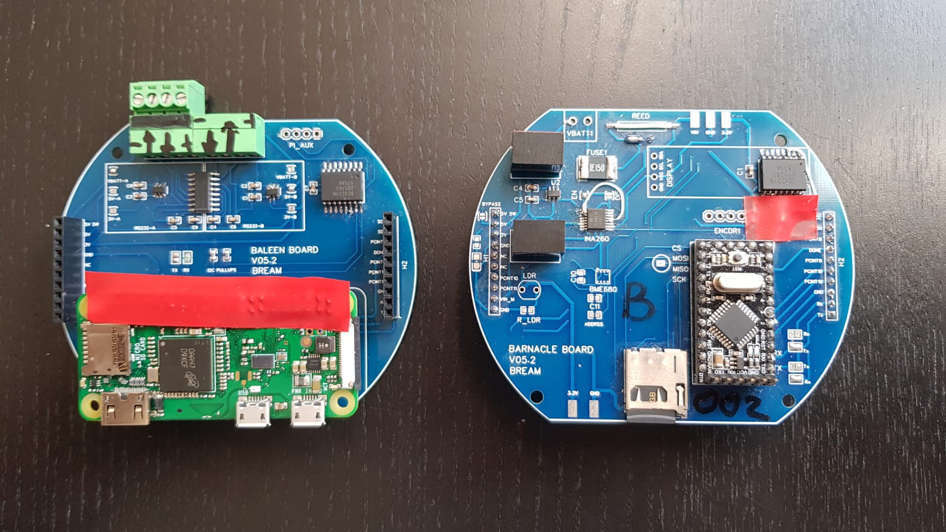
Version 2 (Bream)
The first stacking board approach. Version numbers on the silkscreen don't match this naming convention. This version did see some time in the water, but had a few small hardware fixes. Ultimately- it worked
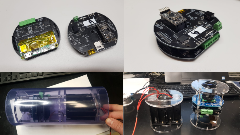
Version 3 (Cod)
This was a iteration of the two board design ended up being one of the most successful versions as it saw the most time in the field ( See: "A short biased discussion on alternatives Part #2" ) . The RS232 interface on the Pi proved to be very useful for a bunch of other applications.
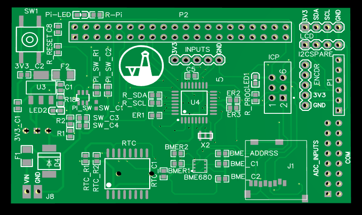
Version 4 (Dory)
From this version things get weird. Although Dory is my favourite PCB for this project so far, it was not successful. The new design gets rid of the stacking PCBs and of the micro-controller in attempt to simplify the control and especially the setup of the sleep interval.
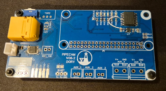
Problems were primarily around getting the RTC to operate correctly without a microcontroller managing it. There where some really fun problems there and I would like to re-visit this design.
Version 5 (Elver)
This was part of my brief foray into ESP32 cameras ( See: "A short biased discussion on alternatives Part #1" ). Although I liked the approach and I LOVE ESP32s, I decided that it sucks a bit of the fun out of the project to keep pursuing it. The "off-the-shelf" solutions were actually just not a good enough fit for what I wanted to achieve. I primarily tested Elver on my bearded dragon's tank.
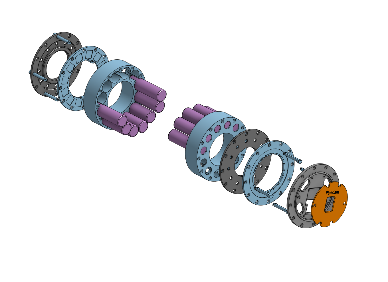
Version 6 (Flounder)
This has been the "current version" since 2023. This is a version where I just use a Witty-Pi on the Pi Zero ( See: "A short biased discussion on alternatives Part #2" ). The Witty-Pi does about 85% of what I wanted to achieve with the "Dory" version and decided to give it a shot. The facts are sometimes "good-enough" is actually just... well... good enough. This also gave me the opportunity to try my hand in addressing some of the mechanical mounting aspects of the project, which is not my strength.
The next post or two will be around this version of the project.
Discussions
Become a Hackaday.io Member
Create an account to leave a comment. Already have an account? Log In.