Myles Eftos
DISCLAIMER: This project plugs in to the mains, which has dangerous voltages and can kill you. Never plug in the device working on this project - you can re-program using an external 5V supply.
I have a Rancilio Silvia coffee machine, that needs time to warm up correctly in the morning - 30 minutes gets everything up to temperature, allowing me to draw excellent coffee shots.
For the past couple of years, I run a simple mechanical timer that turns on at 6am, and goes off at 8am which is fine for the days I go to work, but if I work from home, or it's the weekend, I'm left with a cold coffee machine unless I turn it to manual mode - which often results in me forgetting to turn it off!
To get around this, I'd been planning on getting a smart switch which would integrate with my Home Assistant setup. I looked at the Belkin Wemo, but it seems a little expensive at $80 a pop.
I thought about designing and building my own one, but the prospect of messing around with mains power didn't excite me, nor did 3D-printing a case - 3D printing plastic, by definition isn't very fire resistant.
Browsing Hackaday.io, I stumbled across this project, and it got me wondering if I could find an ESP8266-based Australian WiFi outlet. After a bit of googling, I found something that at least looked the same for $AU20 delivered. Even if it wasn't ESP8266, I could probably gut it and insert a custom board, so I ordered one.
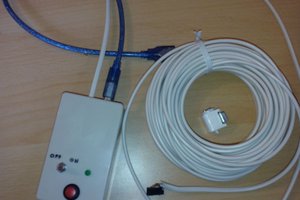
It arrived pretty quickly.
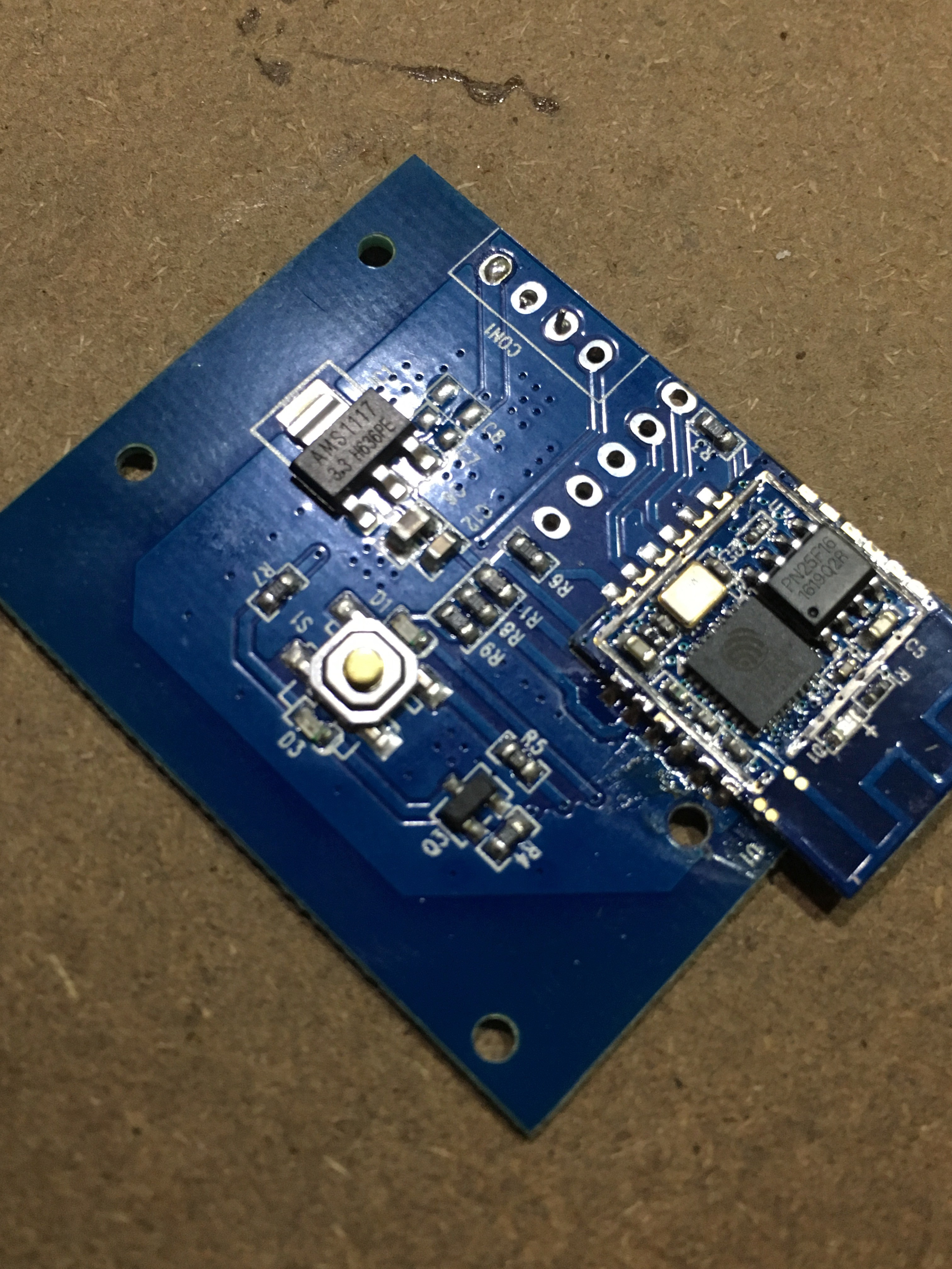
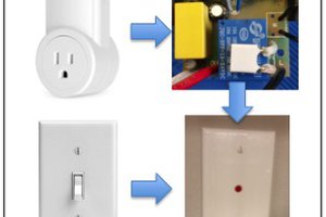
I promptly pulled it apart. There was a daughter board that looked suspiciously like a ESP8266 although the footprint wasn't the same as any reference design I could find.

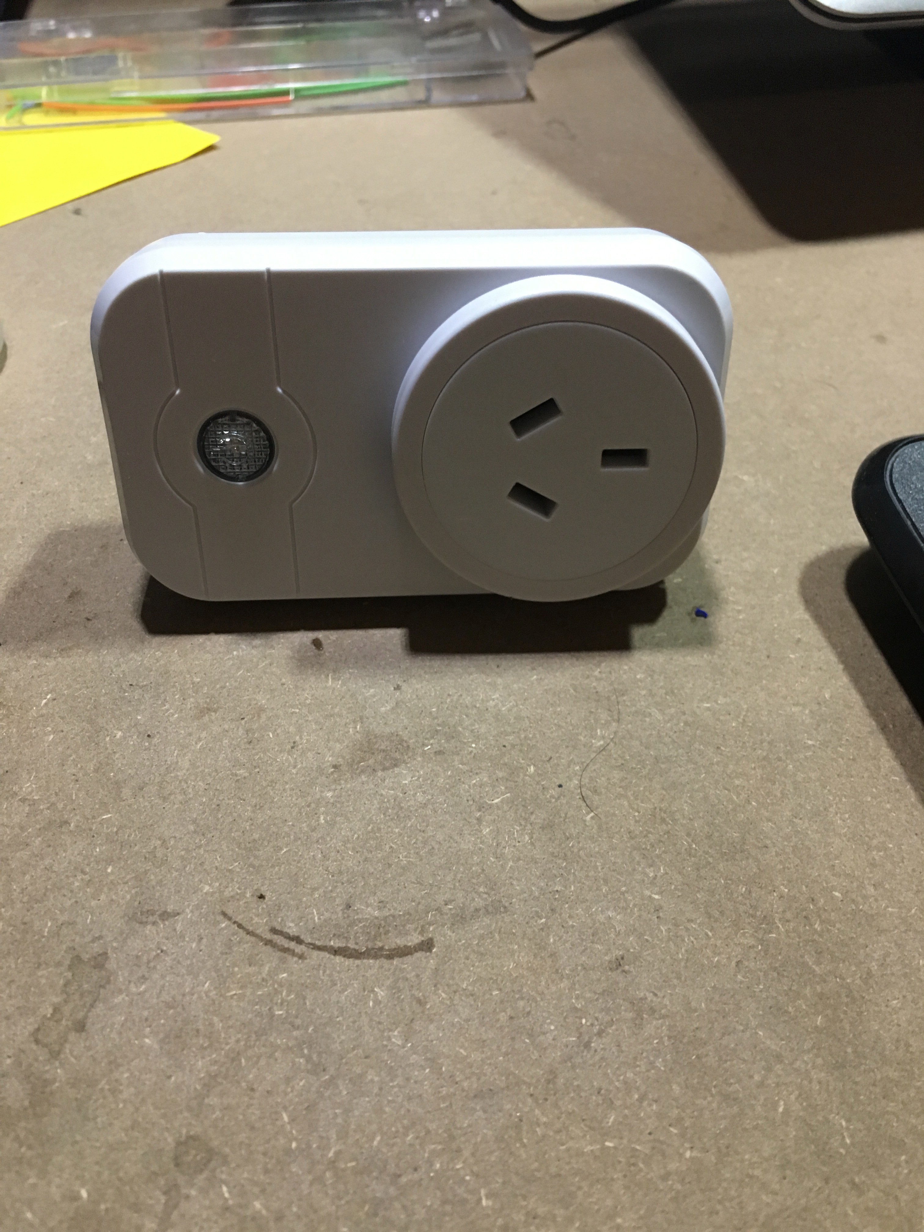
The device
This particular switch has an obnoxious blue LED that is used to indicate power, and network connection (it flashes when not connected). It also has a red LED that is on when the relay is turned on. Finally, there is a button that allows you to turn the relay on and off manually.
Pins
A quick google, and I found the pin out of the ESP8266 chip - now it was just a matter of tracing the wiring back to each LED and the switch. I also needed to find where the TX, RX, Reset and GPIO0 were so I could program it.
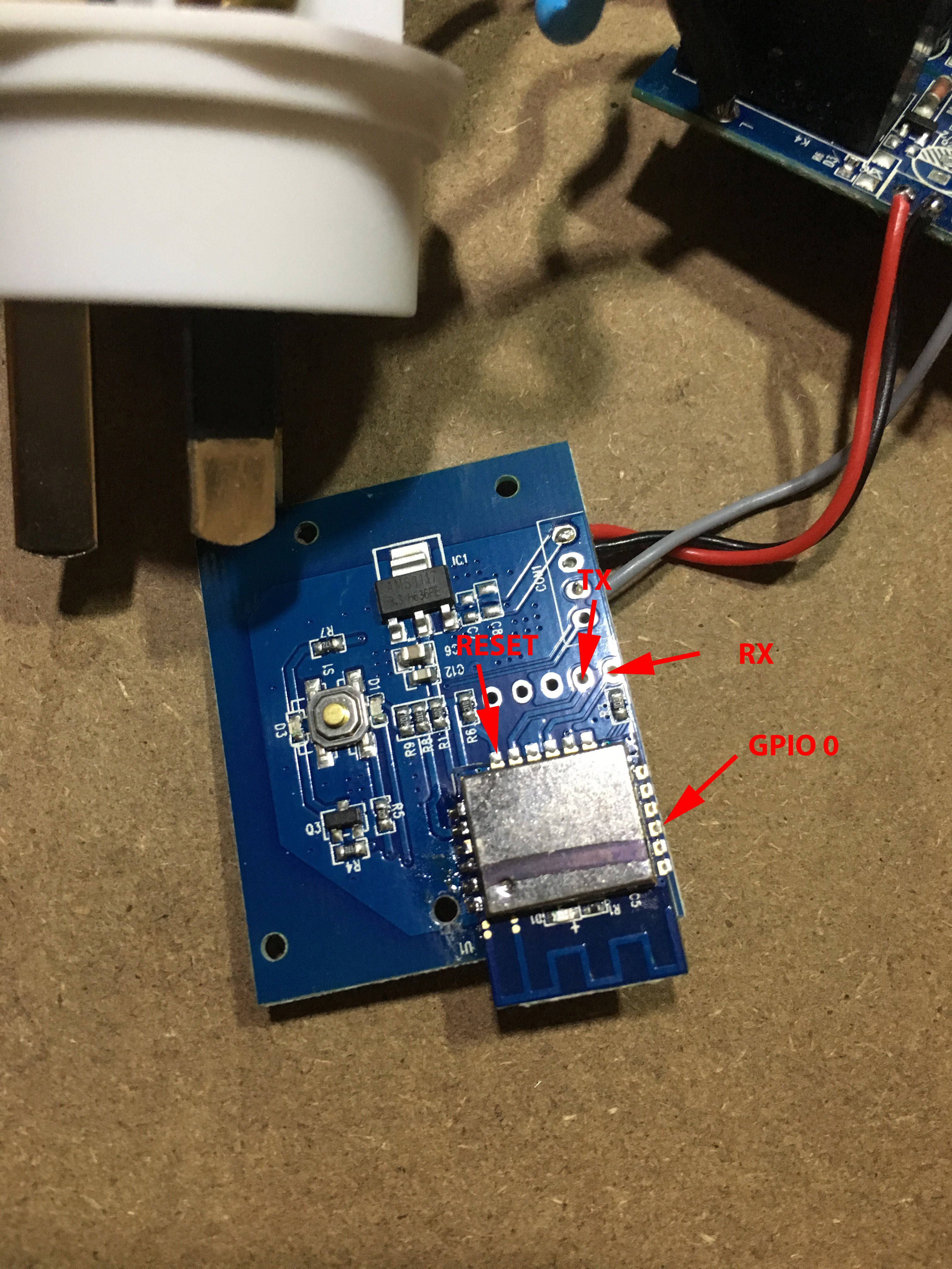
Here is what I found:
- GPIO 4 is the Blue LED
- GPIO 5 is both the Red LED and the Relay
- GPIO 13 is the button
I've marked the TX, RX, Reset and GPIO0 pins on the above image. By wiring these pins up to a FTDI cable, I was able to reprogram the switch, thus freeing me from the shackles of the crappy iOS app, and allowing my home-assistant.io server to talk to the switch.
Now, thanks to a Home Assistant and a NodeRed flow, the coffee machine will turn on between 6:30am and 1pm everyday UNLESS it detects that I'm not home. Nice!
You can see the code that I use (It's based heavily on my garage door opener project).
 Eric Moyer
 mkdxdx
 Ben Brooks