Close
0%
0%

Collision Avoidance and Areal Mapping Drone

A system that detects and avoids objects with ultrasonic sensors

Similar projects worth following
The data from the sensors will be sent from the quad to the RC remote which displays the surroundings on a ili9341 display.

The project consists of a zmr250 quad, 5x hc-sr04 sensors a custom build receiver and transmitter.

The quad

It has a custom built receiver made up of an arduino mini, a mpu6050 (gy87) and a nrf24 module. It can receive but also transmit. This will be used to send the data from the mpu6050 and the hc-sr04s back to the transmitter where it will be displayed.

The transmitter

It consists of an stm32f103 board, an nrf24 module and a ili 9341 display.

Here the data will be processed and a image of the surroundings will be drawn. Also the data can be used to control the quad and avoid obstacles. (not sure if it would be better just to do the obstacle avoidance on the receiver arduino...)

transmitter shown here

I've run into quite some trouble reading out the ultrasonic sensors. I suspected the propellers having something to do with it. 

After a test it's clear that I need to go back to the drawing board on how to accurately read out the distance from the ground.

USSMount.STL

Standard Tesselated Geometry - 999.98 kB - 03/08/2018 at 10:39

Download

USSholder.STL

Standard Tesselated Geometry - 539.93 kB - 03/08/2018 at 10:39

Download

printf.h

h - 601.00 bytes - 06/03/2017 at 21:57

Download

CheapassTransmitter_STM32.ino

ino - 6.24 kB - 06/03/2017 at 21:57

Download

  • 1 × ZMR250 quadcopter frame with motors and escs
  • 1 × cc3d flight controller
  • 1 × arduino mini
  • 1 × stm32f103 Microprocessors, Microcontrollers, DSPs / Microcontrollers (MCUs)
  • 2 × nrf24 modules

View all 12 components

  • First Results

    caBattista06/05/2017 at 19:29 0 comments

    Another day...

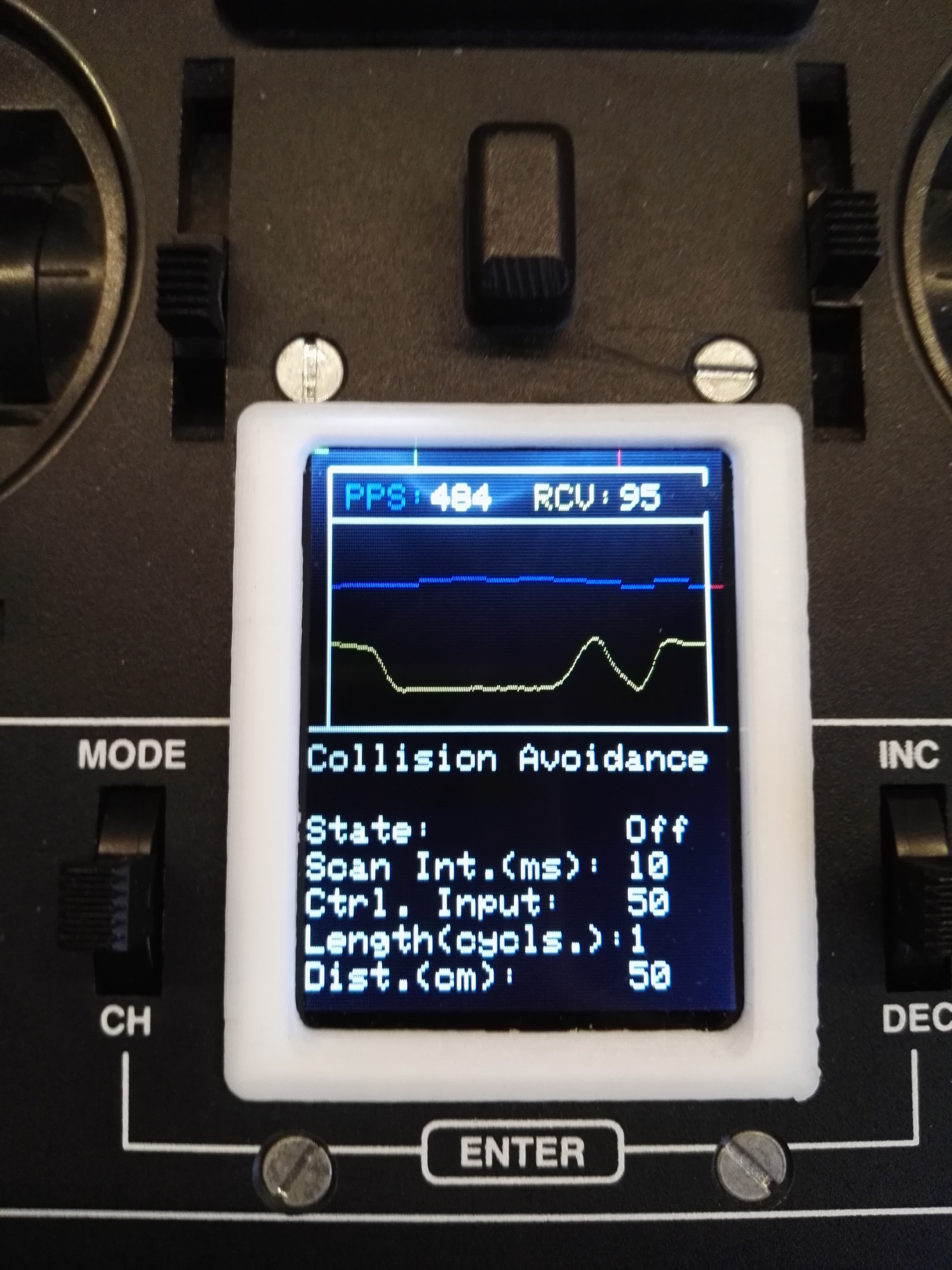
    I added a plotting function on my Controller so I can see the follow the output while flying. By doing that I found out the ultrasonic sensor detects distances between 0-25cm over a concrete floor. A little worse on grass. After that the noise and turbulences of the propellers take over. Now I can at least get an altitude hold of 20cm to work.

    The quad holds altitude by lowering the throttle to a specified value on the controller when the specified height has been reached. This is just a crude proportional controller. A proper PID controller would do the job much better but for now the sensor problems have to get fixed first.

    PPS: sent packets per second, RCV received sensor value in cm

  • Looking at the Ultrasonic Sensor in Detail

    caBattista06/04/2017 at 11:45 0 comments


  • More Flights

    caBattista06/03/2017 at 21:49 0 comments

    After a couple more flights it became apparent that there is an issue with the ultrasonic sensors.

    They work fine on the ground but in the air with the propellers spinning the have a hard time detecting anything. This is likely caused by the noise and air pressure created by the props. when flying. After a little research I found this paper

    http://www.daedalus.ei.tum.de/attachments/article/66/Ultrasonic Sensor Operation on a Quadcopter.pdf

    which reinforces my theory.

    So a little disappointed I bought a sharp IR distance sensor on ebay hoping it won't have the same issues.

    I also just got the rf24 receiver to send back data from the sensors now so tomorrow I can see more precisely where and when the issues start to appear. I've been wanting to add a battery monitor for the quad as well. It would be great to see the battery status on the controller so you know exactly how much voltage you have left without having to rely on these annoying battery beepers.

  • First Flights

    caBattista06/02/2017 at 20:43 0 comments

    The first flight was quite eventful with the quad taking off on its own due to an integer rollover causing the throttle to go from 0 to 255 when I lowered the sticks to much. After a couple of hours bug fixing the code on the controller the quad was finally again maneuverable without any hick ups.

    I added a menu where I could precisely control the variables like distance of the obstacle, time it would override the pitch control, the scan interval and the override pitch value of the collision detection code on the receiver as well turn it off and on remotely of course.

    Now I could finally test how the collision detection was working. And it worked partially. It would set the pitch of the quad to a set value moving it back a little bit from the obstacle. But the ultrasonic sensor was having a hard time correctly detecting it.

    It seems that the position of the ultrasonic sensor isn't ideal because possibly some of the waves bounce off the underside of the quad itself.

    More flights tomorrow...

View all 4 project logs

Enjoy this project?

Share

Discussions

Chauncey wrote 11/27/2018 at 14:54 point

Why not use Laser Radar,it can avoid the influences of the noise?

  Are you sure? yes | no

caBattista wrote 11/27/2018 at 19:36 point

Can you recommend a low cost and light weight laser radar module? I couldn't find any...

  Are you sure? yes | no

Chauncey wrote 11/28/2018 at 02:55 point

TFmini LiDAR,I used to saw it on taobao...about $40 , maybe a little expensive...

But the weight of it is only 5g...

  Are you sure? yes | no

divyesshev3 wrote 10/13/2018 at 14:42 point

Maybe try running the Arduino on external power supply to test with ocilascope

  Are you sure? yes | no

divyesshev3 wrote 10/13/2018 at 14:41 point

Hi... Just to ask could it be because of current drop..when motors are armed

  Are you sure? yes | no

Similar Projects

Does this project spark your interest?

Become a member to follow this project and never miss any updates