-
Small Progress - Energia Not Necessary
06/02/2017 at 03:11 • 0 commentsTonight I just finished creating a JSON index file for the Boards Manager that is compatible with both the Arduino and Energia IDEs. I've successfully tested compilation and flashing through both IDEs. For some reason the current JSON index file was only compatible with Energia, and would cause Arduino IDE to throw java null pointer exceptions. After reworking the file it's properly parsed by both IDEs.
Something learned along the way:
When building a custom JSON index file for theBoards Manager, toolsDependencies.packager should match the top level packages.name value where the tools are described.
For instance when building the new file I had to make in order to have arm-none-eabi-gcc compiler and dslite flasher installed along with this board.
packages.platforms.toolsDependencies.packager = packages.name
I'll post the new JSON in the file section here for anyone interested in seeing a working example. -
Boot Loading...
05/27/2017 at 12:34 • 0 commentsJust wanted to give big THANKS to all who have liked this project and give some insight as to the direction this is going. Lately I've been working on learning the USB boot loader process for this chip with the goal of being able to use it in a similar manner to how Arduino boards do and eliminating the need for a separate LaunchPad dev kit. One really nice features of this chip are the on board drivers in ROM and the already present and active USB-DFU boot loader. It's activated whenever the flash is erased/empty which allows for fresh-from-assembly programming over USB, without the need for an external hardware programmer. It can also be activated directly from user the application with just a few API calls.
My next step is to try and integrate this approach into the Energia flashing process. Being able to flash directly from Energia would truly allow for Arduino-like development on this chip.
-
A Few More Items Completed
05/21/2017 at 01:18 • 0 commentsI completed verifying all hardware PWM and SPI outputs via CCS. I've been creating individual projects for each tested feature. Shortly I'll post these so that they are available to anyone wanting basic examples of how to get each running. They will of course also work on the EK-TM4C123GXL LaunchPad (minus any pinout conflicts).
-
Working Through PWM API
05/19/2017 at 17:28 • 0 commentsWhile working trough verifying each function of the chip I've begun to notice that much of the Energia API for hardware features are actually implemented in software (vs. using the on chip hardware). For instance, PWM. The Energia Servo, or PWM, library is actually implemented manually using general purpose timers rather than the integrated PWM module.
I guess this is fine, but what I'd really like to see is Energia making use of the integrated hardware for these functions. I was tempted to "fix" that and actually spent a few hours attempting to get the TivaC drivers to work in Energia but had no success for PWM. GPIO works though. Ultimately doing this is out of scope for my immediate project so I'll just focus on verifying the rest of the features of the chip and finalize the circuit design and board layout.
-
Hardware Testing Started
05/09/2017 at 02:26 • 0 commentsQuick update - I've tested all GPIO pins in digital output mode through both Energia and CCS v6.1.1 and All pins are functioning correctly.
I did some minor rework on the layout by fixing an incorrect pin assignment for D0 and D1 (they were swapped in the schematic) and slightly enlarging the LEGO sized mounting holes and removing the through-hole plating. The holes were exactly 4.8 mm and did not allow for tolerance in LEGO manufacturing. The hole on the board were cutting into a few of the LEGO pieces I tried on it.
More peripheral testing to come soon.
-
It's Alive!!
05/06/2017 at 01:45 • 0 commentsI built another board today using only the minimal number of components required to support running the microprocessor. I then tested it and got the same result from LM Flash programmer as I had before - No communication with the board. Surely I had made a mistake in my schematic. I decided to take time later today and hit the forums to see if someone else could spot the mistake.
I then had a stroke of inspiration. I had left the VDDA and GNDA disconnected on the two boards I tested, thinking they were not important to the initial board bring up. I decided that I should connect them properly and retest. Well... that was the missing element it seems. Taking a look in the datasheet at section 24.6.1 "VDDA Levels", it clearly states
The POR monitor is used to keep the analog circuitry in reset until the VDDA supply has reached the correct range for the analog circuitry to begin operating. The POK monitor is used to keep the digital circuitry in reset until the VDDA power supply is at an acceptable operational level. The digital Power-On Reset (Digital POR) is only released when the Power-On Reset has deasserted and all of the Power-OK monitors for each of the supplies indicate that power levels are in operational ranges.Lesson Learned: Read your chips documentation thoroughly.
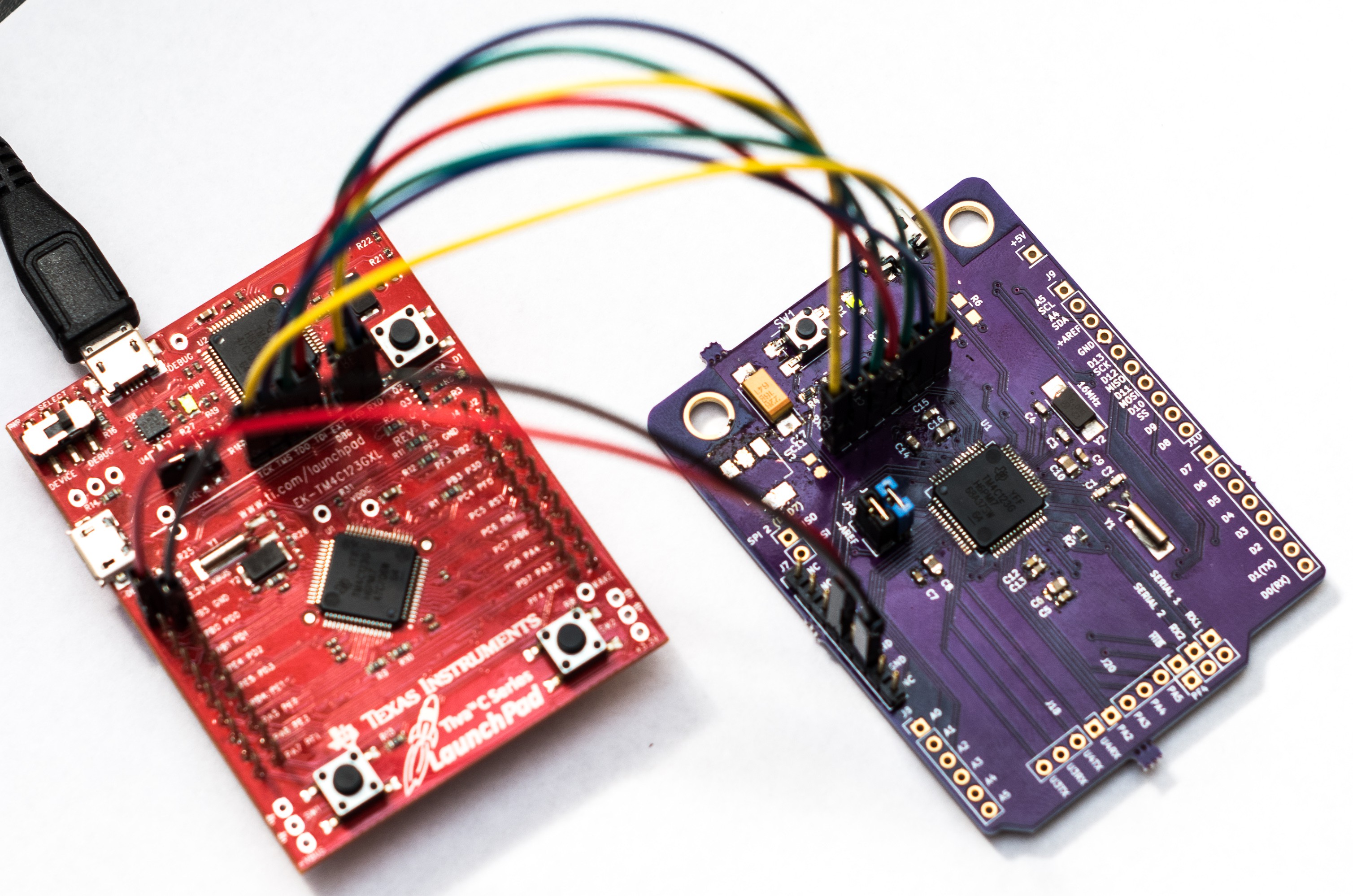
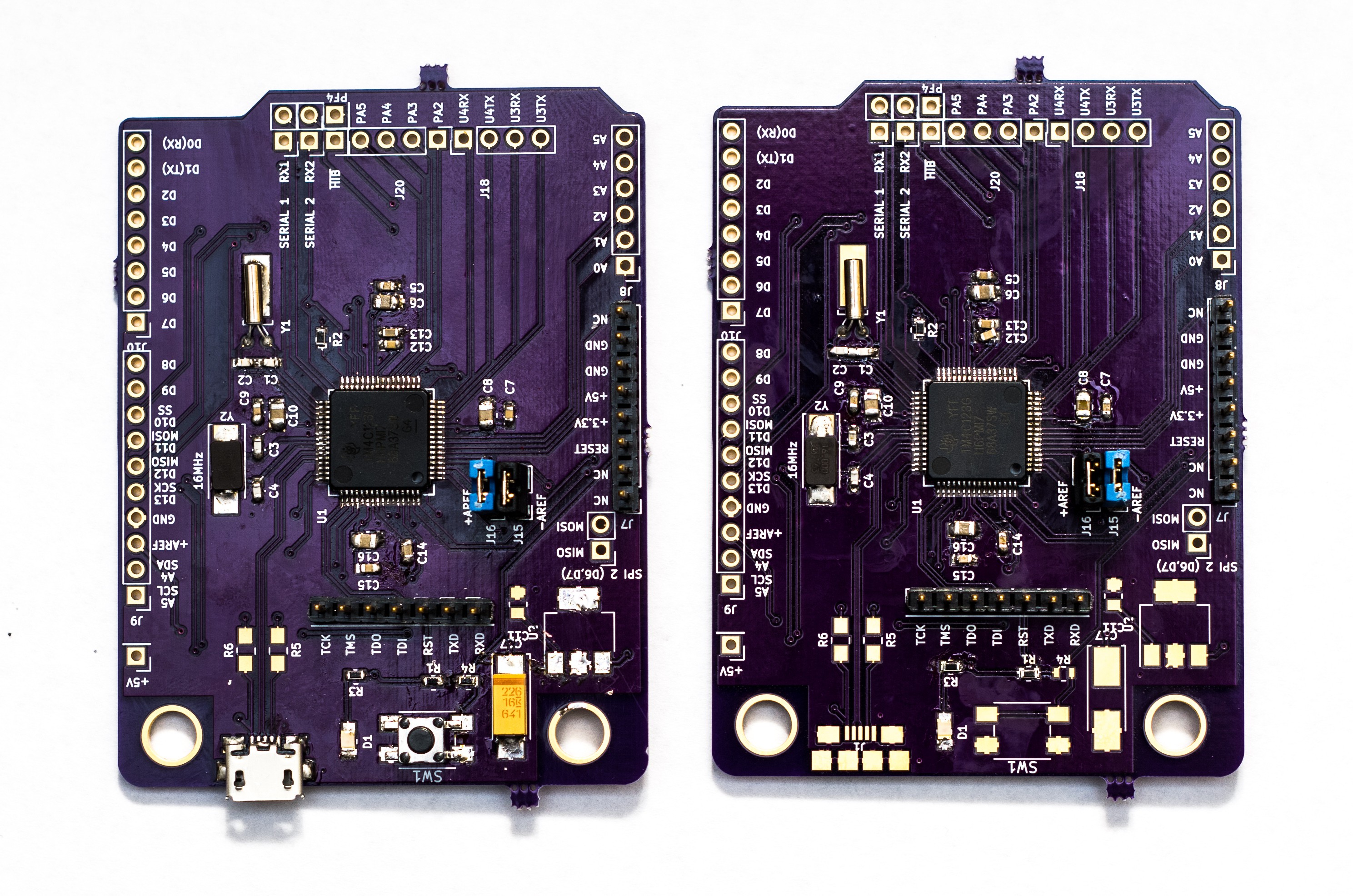
I now have two functioning boards that I can program in Energia and receive serial data over the COMM port monitor. Here are pictures of the the two bards, both in different states of being populated
![]()
![]()
![]()
-
Murphy 2, Me 0
05/04/2017 at 20:37 • 0 commentsSo I sat down to test out the board I build, after removing the 3.3 V regulator, and discovered it was not responding to the debugger. To power it, I was using 3.3 V from the LaunchPad. The LED on my board lit up just fine but the TM4C's internal LDO regulator was not putting anything out on VDDC. I spent a few hours troubleshooting but came up dry. At this point I think powering up the regulator incorrectly caused an electrical problem in the microcontroller.
Next step: Using the third board, build up another circuit with just the bare essentials needed to operate the microcontroller and attempt to program it. If that works, it confirms that the basic support circuitry is correct in my design. If it does'nt work I'll redesign a barebones board to prove out the base design.
-
Live and Learn
05/02/2017 at 17:32 • 0 commentsThe boards arrived on Saturday. I finally had time to sit down Monday night and begin populating one. Full disclosure, this was my first time doing and fine pitch or SMT work. I began by doing a full electrical test on one of the boards, which it passed. I then decided to start with the TM4C since it was going to be the most difficult.
I cleaned the pads with IPA 99 then carefully aligned and taped down the IC with Kapton tape. I put down some liquid flux along one edge, put a blob of solder on my iron and dragged the tip across the pins. That worked well, with the exception of a few bridges that were easily remedied with solder wick. I repeated this three more times all of which had good success except for the last row. Evidently while dragging the iron across the pins I must have pressed too hard because I had bent one of the pins over into its neighbor, to which it was soldered.
I tried flowing solder over it again while bending it back into place with tweezers with no success, except to bend it too far and into its other neighbor. I was left with desoldering the whole IC and straightening the pin, to which I opted to start on another board instead. This time everything went on just fine. So I now have one fully populated board.
With fingers crossed I plugged in the USB connector. The LED did not light up. I checked for the 5V USB rail. It was there. I checked for the 3.3V regulator output. It was not there. What could possibly be wrong. Did I ruin the component while soldering it down? I decided to take another look at my schematic , end eventually took a look at its datasheet. And there it was, staring me in the face. The part & footprint that I had place in the schematic was the wrong one. I had simply renamed it to be the part I was actually using, which of course had a different pin assignment.
So now I'm off to fix this issue with some deadbug style soldering. I've fixed the schematic locally, but still need to commit and push it to the git repo.
Lessons Learned
- Practice soldering similar components before attempting it on your actual board.
- Double check your datasheets and schematics before sending your boards to the fab shop.
-
Boards Received
04/30/2017 at 12:27 • 0 commentsI received the boards in the mail yesterday. When I get a chance today I'll take a picture of them to post. At some point this week I'll do a basic electrical test and begin to populate one.
-
Boards are on the way back
04/27/2017 at 00:49 • 0 commentsI was just notified by OSH Park today that they received the panel containing my boards from the fabricator. They also shipped them out today and are expected to arrive here by Saturday. Yay!
Roadrunner (the Arduino-Tiva)
An Arduino clone based on a TI's Tiva TM4C123G (An 80Mhz ARM M4F with USB OTG)