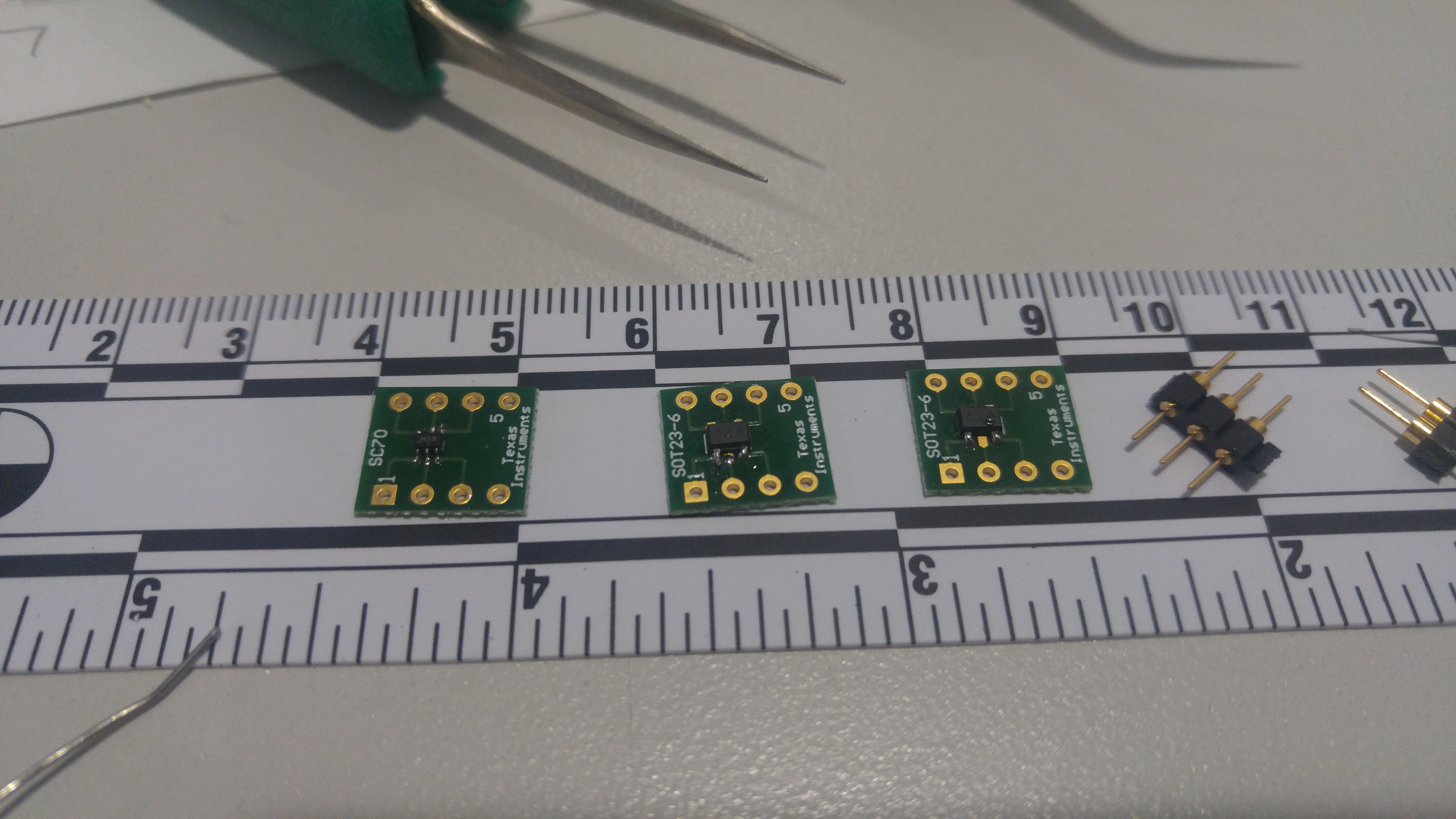
I have recently received the order of components to breadboard the first prototype.

Initial testing has shown something interesting and unexpected. The linear voltage hall effect sensor when powered on has a baseline output of ~1.64v. If i place a North facing magnet on a surface and move it towards the sensor, the voltage output initially decreases. I decided to measure and graph the outputs. Based on the results, with the test magnet, at about 10mm the voltage breaks the 1.64v threshold. I will basically have to slightly re-think my approach and set any value above this threshold to be a valid input to the board logic. More to come soon...
Note: When dealing with SMT, always buy extra... Because somehow they end up jumping onto the floor and vanish.
Video featuring Allegro A1318 Hall effect sensor voltage threshold testing:
 Deviza
Discussions
Become a Hackaday.io Member
Create an account to leave a comment. Already have an account? Log In.