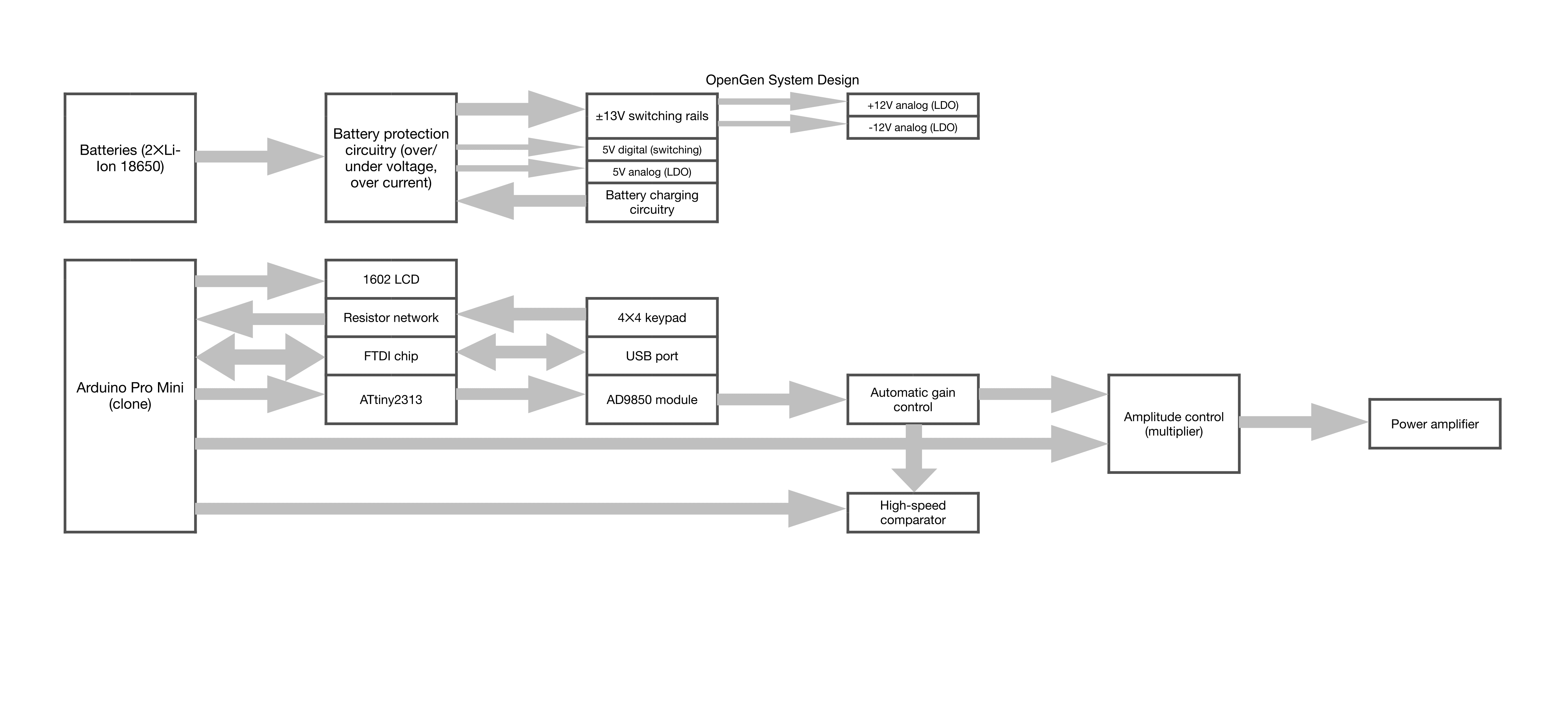
R2 system design (zoom in or download the pdf from the dropbox link in the files section)

2- minute introduction video
(Link: https://www.youtube.com/watch?v=KSRnfjIvhYc)
All design files can be found here or at the 'all project files' link in the sidebar. CAD files are in OpenGen/CAD files.
The following is now completely up to date with the new R2 design.
OUTPUT
OpenGen can output sine and square waves from 3kHz to 42.5MHz in increments of 0.0291Hz. The square output triggers from the sine so they cannot be different frequencies. There is a load switch (pushbutton controlling a relay) for each output to disconnect a load easily. The analog parameters (sine amplitude & offset, square duty cycle) are adjustable to an 8-bit resolution (2^8=256 steps).
- Sine wave output: amplitude from ±39mV to ±10V and DC offset up to 10V. Note that the maximum output is just over ±10V so you cannot have maximum offset and amplitude at the same time. Maximum output current: 200mA.
- Square wave output: selectable 3.3V or 5V peak voltage with adjustable duty cycle from 0.39% to 100% in steps of 0.39%. Maximum output current not rated (no info in the comparator's datasheet), but recommended >10mA.
POWER
There are two 3.7V lithium-ion 18650 cells inside OpenGen. First each cell goes through its own BQ29700-based protection circuit and then they are wired in series. The batteries power an LT3471 (dual switchmode power supply controller) which generates ±13V rails. Each rail then goes through a precision LDO to make them (collectively) low-noise ±12V rails. As well as this, there is a switching 5V digital rail and an LDO 5V analog rail.
Battery charging is handled by a BQ2057T 2-cell battery charger which charges the batteries at 1A. It requires an input of 8.5V or more (9V plug pack).
Power consumption is mostly dependent on the LCD backlight level and the output power. Specs will come in the future but a rough guide would be 1W minimum to 8W maximum.
PERIPHERALS
Frequency and other parameters are input using a 4✕4 membrane keypad (like this one). There is a 16✕2 character LCD (with an adjustable backlight) which displays the interface.
HARDWARE
- The brains of OpenGen lie in an Arduino Pro Mini clone running an ATMEGA328 at 16MHz.
- The Arduino Pro Mini clone interfaces with an ATtiny2313 which drives the AD9850 module. Having a separate microcontroller for the AD9850 module allows much faster update speed during frequency sweep mode.
- The AD9850 is wired in a parallel configuration to the ATtiny2313 to allow maximum frequency update speed. For the same reason, the ATtiny2313 is clocked at 20MHz.
- The LCD is a standard '1602' type (16 columns and 2 rows of characters). It is controlled over I2C using a PCF8574 port expander.
- The sine output of the AD9850 first goes through an automatic gain control (AGC) circuit which takes a 300mV-1V pk-pk input and gives a 3.6V pk-pk output. After that it goes through an analog multiplier which controls output amplitude, and then a high-speed power amplifier. The power amplifier is a THS3001 (A=2.5) and THS3095 (A=2) 'daisy-chained' to give a gain of 5.
- The square wave is generated by a comparator (TLV3501) which takes the sine wave AGC output and an input from the MCU which controls duty cycle. The power is switched by an adjustable precision LDO and an analog switch.
SOFTWARE
The software for the main MCU will be written in the Arduino IDE and therefore will be easily adaptable. It can be uploaded using the ISCP header on OpenGen (be sure to remove the PROG jumper link). The software for the ATtiny2313 will be written in Atmel Studio to allow access to lower-level functions to speed up operation. It can also be uploaded in a similar fashion with a different ICSP header.
Due to the nature of the software-controlled AGC (Automatic Gain Control) in OpenGen, the lowest frequencies (i.e., sub 100Hz) are already attenuated by around 5.7dB, reducing the level of further attenuation available. The level of 'pre-attenuation' grows lower as the frequency increases.
There is an on-board I2C bus which interfaces with the LCD and the DAC.
LICENSE
Everything in this project is Public Domain. That means I have no rights over the information I publish, and consequently you can do whatever you want with it! I would appreciate it if you drop me an email at richard{AT}microbug.co.uk if you find this project useful or would like to contribute.
 Richard Coleman