 Sanpi
SanpiThis lab includes:
- a variable power supply (DPS5015);
- a fixed power supply (LM2596);
- an oscilloscope (redpitaya);
- a signal generator (redpitaya).
This box also include a raspberry pi 3 with a touch screen to control the redpitaya.
Already have an account? Log in.
To make the experience fit your profile, pick a username and tell us what interests you.
This lab includes:
This box also include a raspberry pi 3 with a touch screen to control the redpitaya.
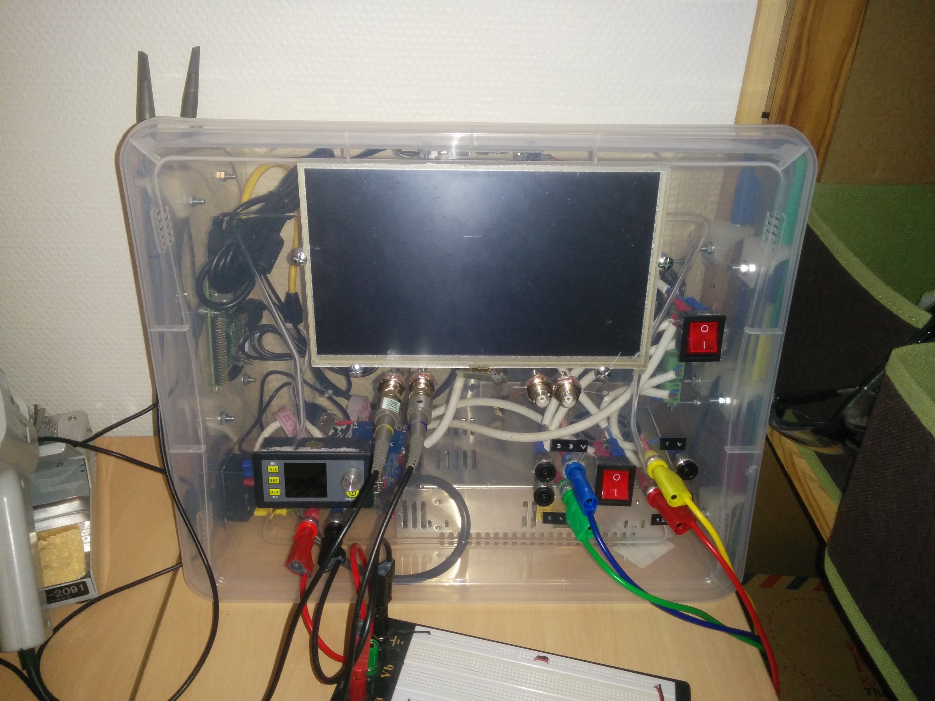
Long time without news, but I continue to work on this project.
First, I abandoned the idea of a 3D printed case, and I bought a plastic case and do some holes into.
Second move, I discovered WaveForms, an open-source software for digilent tools but works with a documented Digilent Instrumentation Protocol. I started to write an implementation for redpitaya and it’s probably easier to write than a complete software.
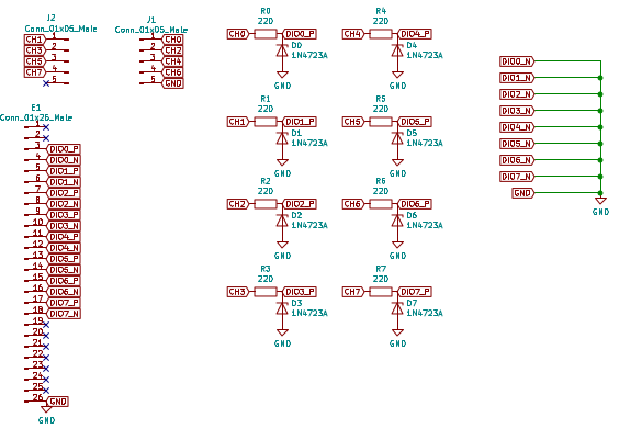
And the last, I started working on logic analyzer feature for the readpitaya. It’s a documented feature, but It seems require (for my STEMlab 125-14) an expensive extension board (I already have the application). After reading how a logic analyzer works, I just create a simple shield with zener diodes to protect inputs:
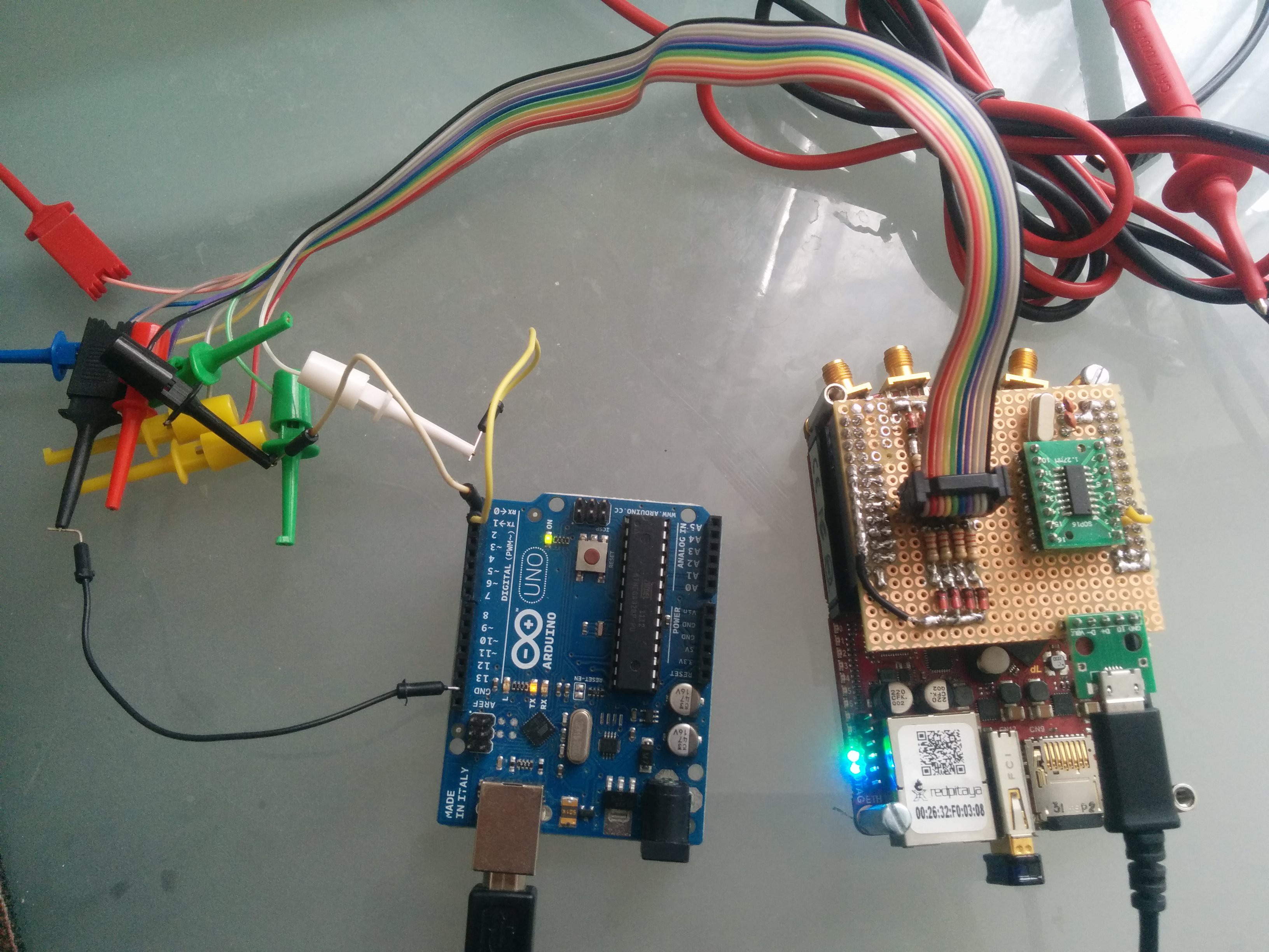
The prototype board:
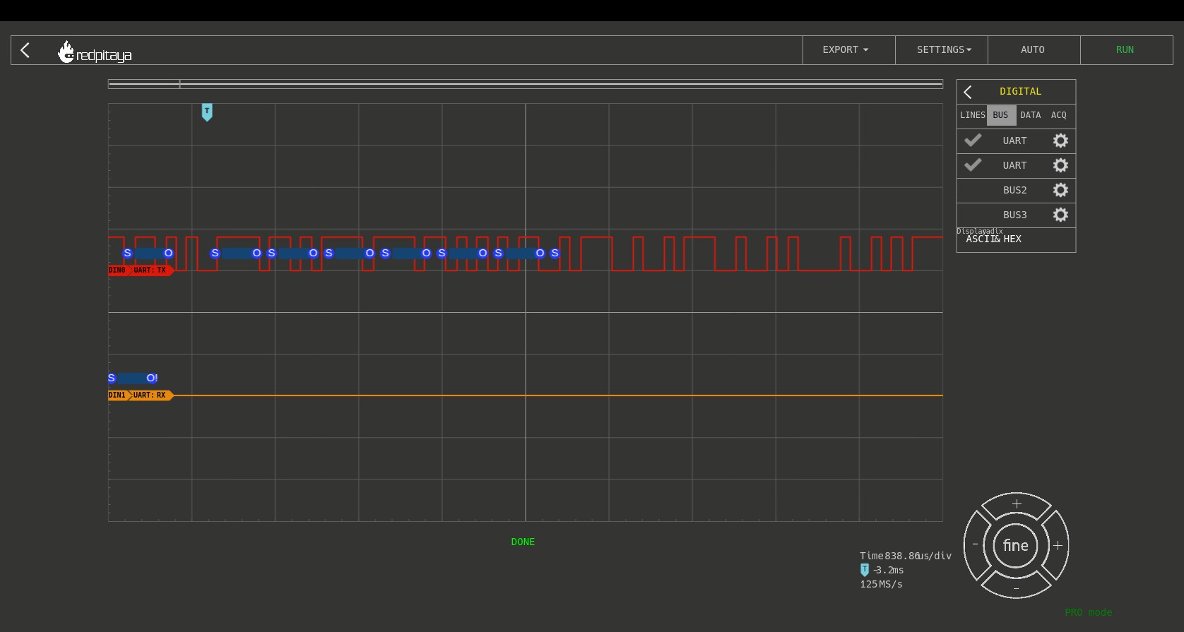
And the result:
I am rather satisfied with the result (I didn’t destroy my redpitaya!) except the decoding doesn’t work.
You probably see the ship on my proto-shield. It’s a UART/USB converter, the next step is to implement the SUMP protocol to allow to use PulseView if you don’t have the chance to have the official application. WaveForms supports logic analyzer, but with out decoder.
The wiring is tedious and requires small finders,but that works fine :)
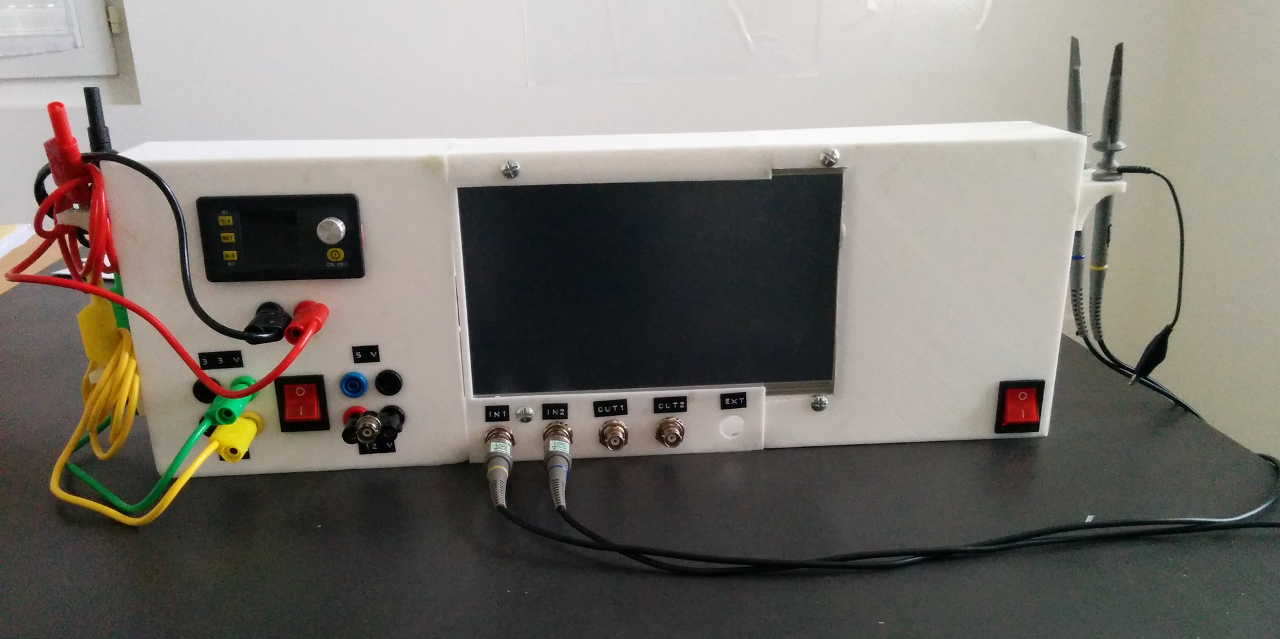
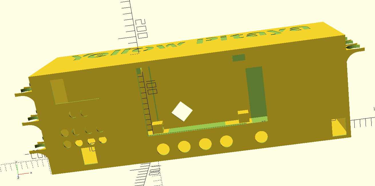
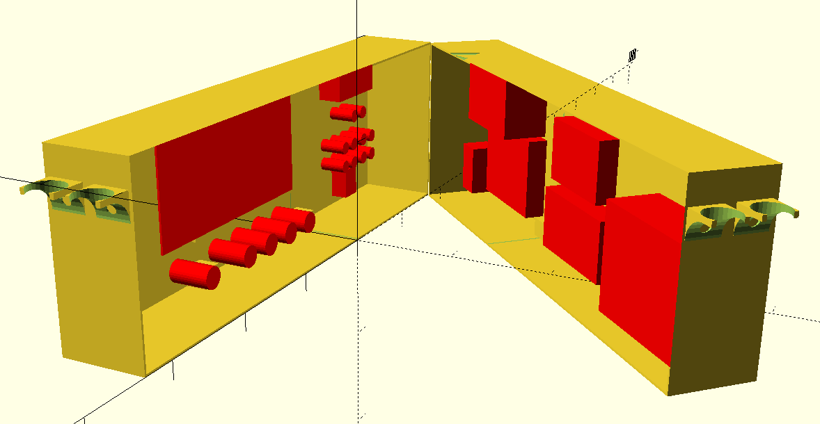
Another good step passed :) I print all front parts of the enclosure.
Except a "little" omission (the hole for the screen on the right part) all fit correctly. I use the dremel to fix that instead of reprint this part because it’s long (about 14 hours) and I already planned enhancements for this part (a multimeter or buttons to control the oscilloscope).
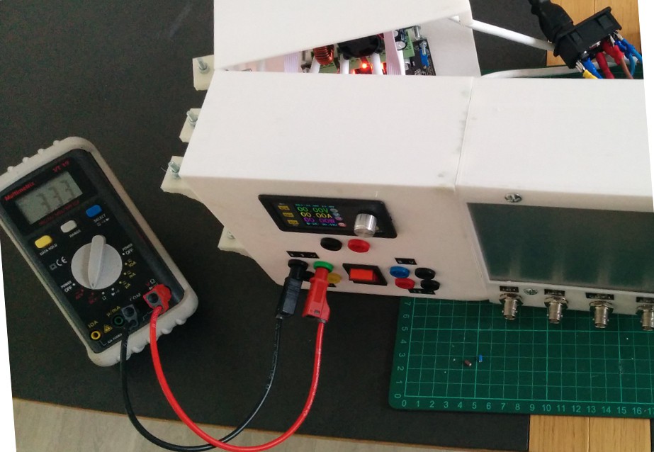
I have received the new touchscreen, it’s time to test yellow pitaya in real contiditions. It’s an important step for me, because it’s the basic idea of this project: adding a touchscreen to a redpitaya.

This is not perfect (I currently have a huge preformance issue with data retreiving) but it’s very intuitive to use.
The redpitaya configuration is made via ansible. The recipies are available here.
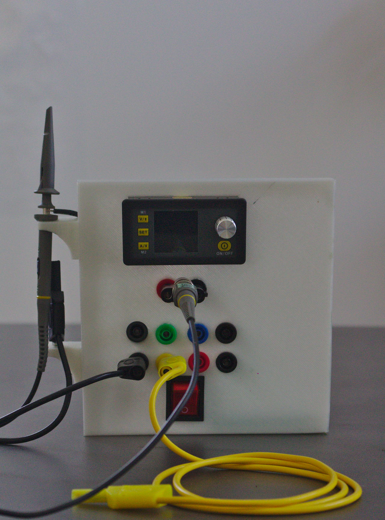
It’s not perfect, but it’s a good first print. The DPS module doesn’t fit correctly and the screw supports to assemble parts are not really printable. I probably review the layout of this module (the power button is too close from plugs) but I’m very surprising by this first try.
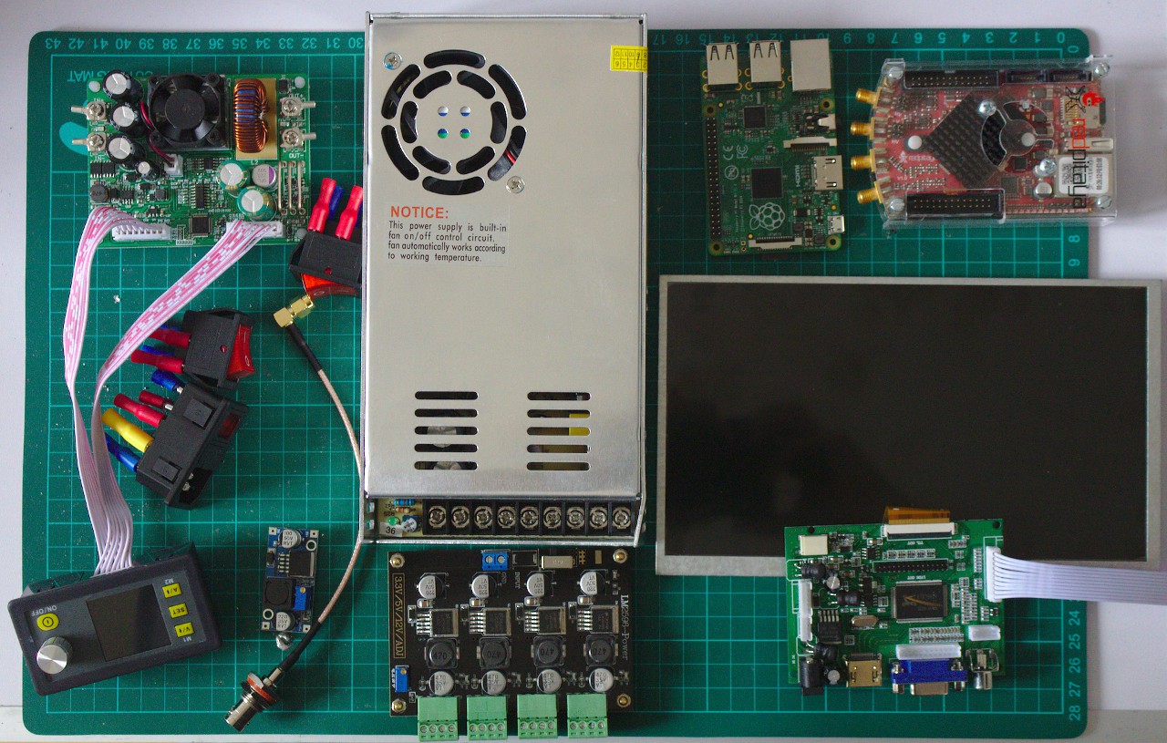
All hardware pieces are here, almost… Because the screen doesn’t work (another is on the road) and I also need a STLink for flashing the DPS 5015. But I already can assemble some pieces and create the plan for the case.
During the frontend redesign, I found some bugs in the SCPI server. I was able to fix a simple buffer overflow in ACQ:SRAT? command. It’s not a big problem, because I can use the ACQ:DEC? instead. But there is more boring bugs. For example the binary output format and voltage getters (amplitude and offset) doesn’t work.
I have already written a binding for the redpitaya C api for fun (it’s my first crate idea) thus it’s easy to create a TCP server to handle strings.
After two weeks of work, including a big segfault fixing, I publish a new SCPI server, compatible with the legacy server.
This server pass all scpi client tests (± f32::EPSILON of course) :
$ cargo test -j1 -- --test-threads=1
    Finished dev [unoptimized + debuginfo] target(s) in 0.0 secs
     Running target/debug/deps/redpitaya_scpi-a9e9b34583454096
running 42 tests
test acquire::test::test_average ... ok
test acquire::test::test_decimation ... ok
test acquire::test::test_gain ... ok
test acquire::test::test_sampling_rate_get_buffer_duration ... ok
test acquire::test::test_status ... ok
test analog::test::test_reset ... ok
test analog::test::test_value ... ok
test burst::test::test_count ... ok
test burst::test::test_mode ... ok
test burst::test::test_period ... FAILED
test burst::test::test_repetitions ... ok
test data::test::test_buffer_size ... ok
test data::test::test_get_write_pointer ... ok
test data::test::test_get_write_pointer_at_trigger ... ok
test data::test::test_read ... ok
test data::test::test_read_all ... ok
test data::test::test_read_latest ... ok
test data::test::test_read_oldest ... ok
test data::test::test_read_slice ... ok
test data::test::test_set_format ... ok
test data::test::test_units ... thread '' panicked at 'called `Result::unwrap()` on an `Err` value: "SendError(..)"', /checkout/src/libcore/result.rs:859
ok
test digital::test::test_reset ... ok
test digital::test::test_set_direction_in ... ok
test digital::test::test_set_direction_out ... ok
test digital::test::test_state ... ok
test generator::test::test_amplitude ... ok
test generator::test::test_arbitrary_waveform ... ok
test generator::test::test_duty_cycle ... ok
test generator::test::test_form ... ok
test generator::test::test_frequency ... ok
test generator::test::test_offset ... FAILED
test generator::test::test_phase ... ok
test generator::test::test_reset ... ok
test generator::test::test_status ... ok
test generator::test::test_trigger ... ok
test generator::test::test_trigger_all ... ok
test generator::test::test_trigger_source ... ok
test trigger::test::test_delay ... ok
test trigger::test::test_delay_in_ns ... ok
test trigger::test::test_hysteresis ... ok
test trigger::test::test_level ... FAILED
test trigger::test::test_status ... ok
failures:
---- burst::test::test_period stdout ----
	thread 'burst::test::test_period' panicked at 'assertion failed: `(left == right)` (left: `Ok(999999)`, right: `Ok(1000000)`)', src/burst.rs:176
note: Run with `RUST_BACKTRACE=1` for a backtrace.
---- generator::test::test_offset stdout ----
	thread 'generator::test::test_offset' panicked at 'assertion failed: `(left == right)` (left: `Ok(0.30004883)`, right: `Ok(0.3)`)', src/generator.rs:418
---- trigger::test::test_level stdout ----
	thread 'trigger::test::test_level' panicked at 'assertion failed: `(left == right)` (left: `Ok(0.4000244)`, right: `Ok(0.4)`)', src/trigger.rs:221
failures:
    burst::test::test_period
    generator::test::test_offset
    trigger::test::test_level
test result: FAILED. 39 passed; 3 failed; 0 ignored; 0 measured
error: test failed, to rerun pass '--lib'
This project was born from an observation: I rarely use my redpitaya. After a little reflexion, I supect two points:
This is why I imagine put my redpitaya in an old cathodic oscilloscope case, controlled by a touch screen maybe with some buttons. But before buying some stuff, I need to verify if I can create a new application to display oscillograms.
I tried to undestand how create a web application, but html and javascript isn’t my favorites languages. And I found how can I remotly control my redpitaya with the SCPI protocol. Great! After writting a client in rust I have written a frondent application (also in rust).

After one month of development, that works fine, not perfectly but good enough to command other pieces of hardware.

Can you create a new issue on https://github.com/yellow-pitaya/scpi-server/issues with the SCPI commands, I can try with both server.


 DoctorDre
 Victoria
 Central Space Alliance
Great project, I am working in doing a Labview client (scpi) the first I did is use the examples from ni.com site, blinking LED's is working fine means I have good connectivity but I am having trouble with the acquisition and generation, in the first I get TCP error 56 after the first set of samples and with the generator I get a distorted sine wave, I am wondering if this is a problem with the scpi server, what do you think? do I replace it with yours?
Thanks