 Wassim
Experimentation setup
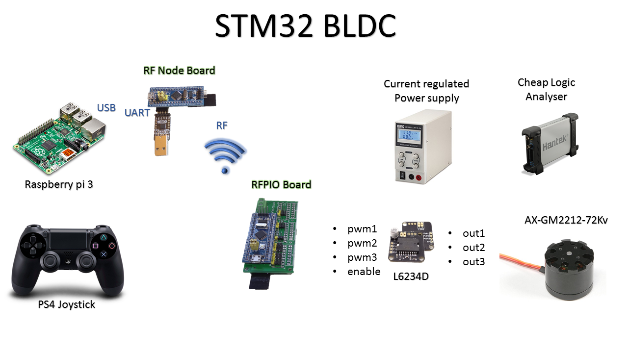
- The PS4 Joystick is a good way to manipulate multiple variables simultaneously which is suitable for experimentation. The touch pad adds possibilities for position reference.
- The Raspberry pi here is not needed for the BLDC control but is acting as the Joystick interface plus its development environment is more suitable for programming.
- Although the RF Node Board has a USB built in, the USB SW is complicated to integrate and uses memory, so the UART has still time to live in experimentation. A USB to UART brings it down to the same.
- The RFPIO Board was intended for servomotors control not BLDC, but is a good platform for BLDC experimentation as it exposes the PWM outputs and has radio connection.
- The Radio connection is not of much use here, but it is actually practical and very important isolation medium between the Test PC and the motor test bench. That advantage is not used here but only because the power supply has regulated current.
Note on Safety:Using a normal battery with experimental controller is dangerous and might lead to the test bench catching fire. Use either a fuse, a current limited power supply or a reliable controller. |
- A cheap logic analyzer is being used in the button mode that works with the Saleae Logic SW which is a great and affordable combination for analysis.
- A commercially ready module is used for the L6234D from eBay, but this one does not offer much options as all enables are joined together and there are no sensing resistances. So this can only control in Open Voltage Loop.
Demo
The interesting part in this demo is not the revolution of turning a bldc for the first time, rather :
- The integration of such a number of small peaces of SW on different environments
- The approach how someone could have a feeling of how a BLDC motor works by directly manipulating multiple variable and seeing the pulses on a logic analyzer
Open Loop Control : BLDC = Stepper motor
- It is always possible to change the voltage in every coil without regarding the position of the rotor.
- That definitely would result in missing steps if the voltage is not enough to deal with the torque. As in BLDC steps are big, missing them do hurt and does not go unnoticed.
- The solution is to increase the voltage, but then you're wasting energy that does not go in torque but in flow to maintain the motor position. The current is much higher when the motor is at rest due the absence of counter electro-force.
- The used BLDC motor here consumes around 50 mA at a speed of few rotations per second and up to 180 mA at a stopped position with 7.2 volts.
Control Parameters
Every new video or diagram about BLDC control allows me to understand something more, that's why, in spite of the number of documents and tutorials in the internet, why not add another simple view on this.
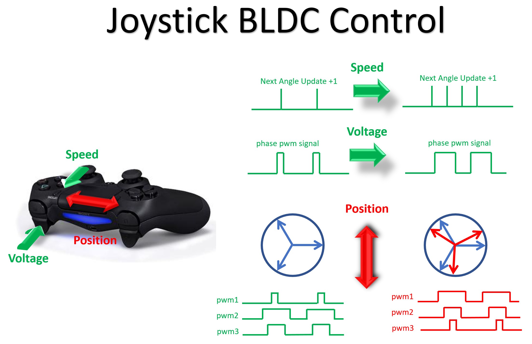
- The speed acts on the delay before applying the next electric angle position, note that the maximum command update frequency is less then the pwm signal frequency otherwise it is useless (figure not of same scale for both).
- The voltage is increasing the pulse width. Although only one pwm signal is displayed here, all of the 3 signals proportionally increase and decrease their width pulses.
- The position is even simpler from software point of view as you just have to increase or decrease the electrical angle proportionally to the movement of the finger on the touch pad. The sinus of every angle is taken to define the pulse width of the corresponding bridge.
Software
Sorry for placing source code as pictures but the source code plugin is so lame that the code is barely readable, so I keep the VSCode colors.
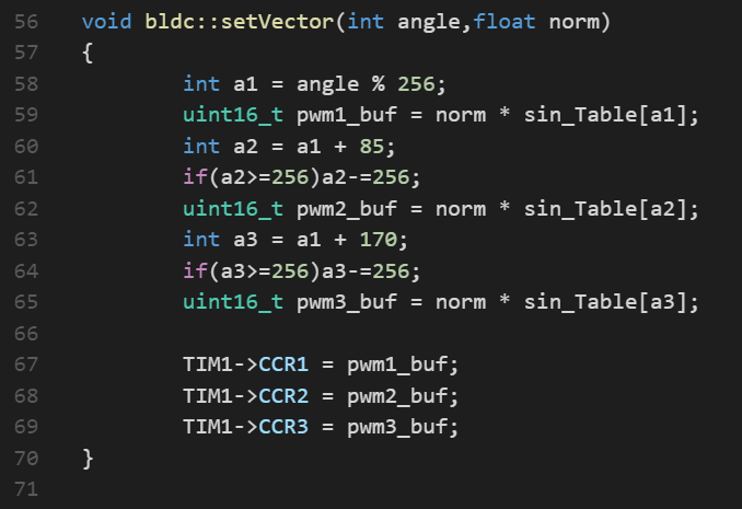
All the bldc magic is here. The angle is taken as an int to make it simpler, I'm not even using a proper unit as radions or degrees rather a 256/360° units so that it fits a 256 table where the sinus is porecessed once and stored as lookup.
- The live calculation of floats with this M3 running at 72MHz took 7.2 us while the lookup function here just around 1 us so it is still worth it for a 50 us pwm period = 20 KHz (maximal control refresh rate).
- Note that the L6234D can go up to 150 KHz from the dead switching time point of view.
- I am using the mbed-os as development environment so why not simply use ?
PwmOut pwm1;

pwm1 = 1;
Well, that is good for an out of the box configuration and initialization. It does everything for you, from the cmsis HAL api calls to the calculation of which pins should be assigned to which alternate functions. It configures the pwm mode, all of that stack goes through the overload of that assignment operator which would have brought the function time from microsecond to millisecond.
That's why you see the direct usage of the registers which is around one instruction.
Signals
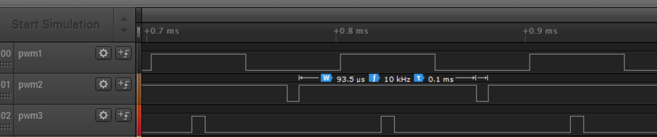
- We can see the center aligned pwm signals on the logic analyzer.
- Note that the frequency is displayed as 10 KHz not 20 KHz mentionned above, which is correct as sticking two pulses together reduces the variations to half.
Conclusion
Once you control the speed and voltage simultaneously, you get a better feeling on when the motor stalls and misses steps, you can hold it and apply a higher voltage to see when it overcomes the torque applied. That is not science, but that is the experience that makes you comfortable to deal with the rest of the scientific formulas.
Next steps would be to look on a torque control loop, then maybe Back-EMF monitoring, designing a specific extension board for BLDC and meditate in front of Field Oriented Control videos. But what is sure is that for my plans of inverted pendulum mobile robot, this control is already enough.
Discussions
Become a Hackaday.io Member
Create an account to leave a comment. Already have an account? Log In.