The first revision of the hardware has been built and basic firmware which configures the sensor and outputs sensor readings over USB and UART has been written. The good news- it's functional. The bad news- this won't be the final hardware revision.
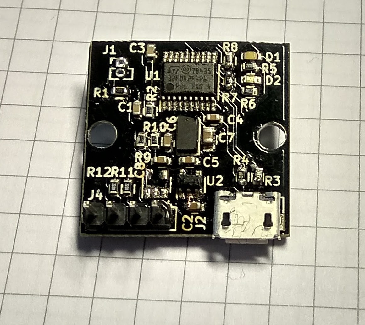
The assembly is not too pretty due to having it reworked multiple times- the initial components were soldered in toaster oven, but I soldered the VL53L0X after that, from some other boards I had been working on.
There are three fuckups hardware changes:
- For some reason, I assumed that voltage regulator's enable input can be left floating. Oops, it has built in pulldown resistor, so I needed to tie the enable input to Vin.
- While PCB was being manufactured, I decided to test VL53L0X sensor operation from 3.3V, as I noticed that many other projects around it don't bother with powering the sensor from 2.8V in 3.3V systems. I could not discern any measurable performance difference (the power dissipation seemed to be a bit higher but that does not matter in this project).
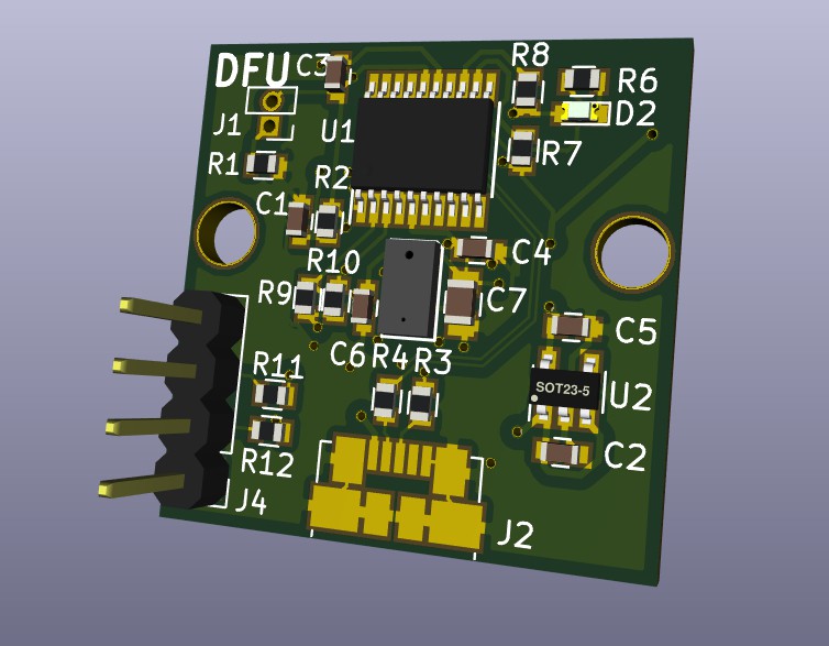
- Selecting DFU mode with BOOT0 pin requires high voltage level, but I had wired ground to jumper's other pin.
- As I'm pretty sure USB will be the main reason someone would use this board instead of plain breakout board and having some unused space on board due to removing the other regulator, I wanted the USB connector to be centered.
The new hardware revision has already been produced and is now being shipped to me.
Discussions
Become a Hackaday.io Member
Create an account to leave a comment. Already have an account? Log In.