 Pauli Salmenrinne
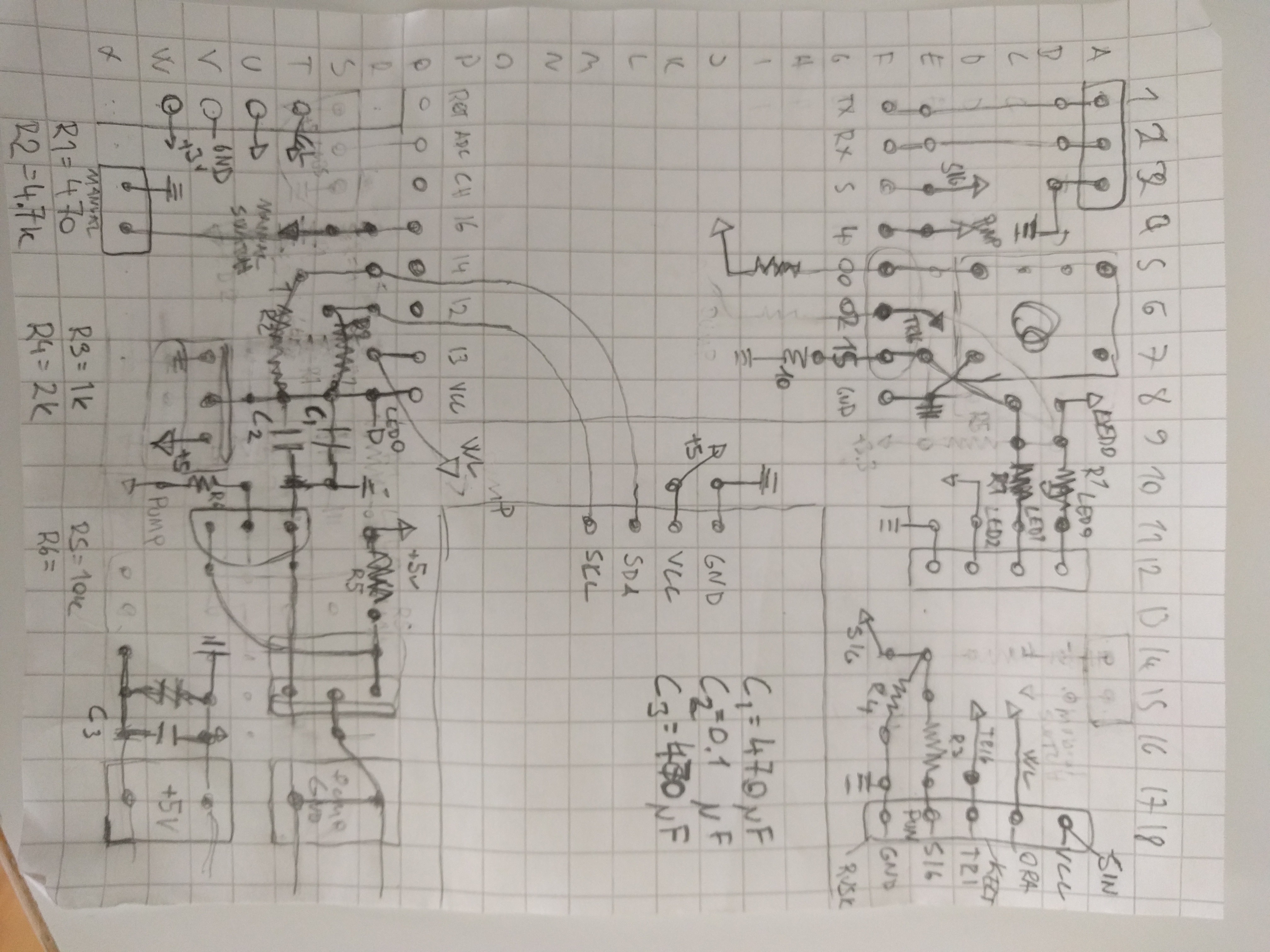
Here is the hand drawn circuit diagram, i'll document it here since i am going to loose the original one anyway. Pins are proper but changes were made on the X1 corner to fit the caps, and the push button was replaced with a jumper for space - since the rtc needed to be moved upwards to make space for 'screw headers'.
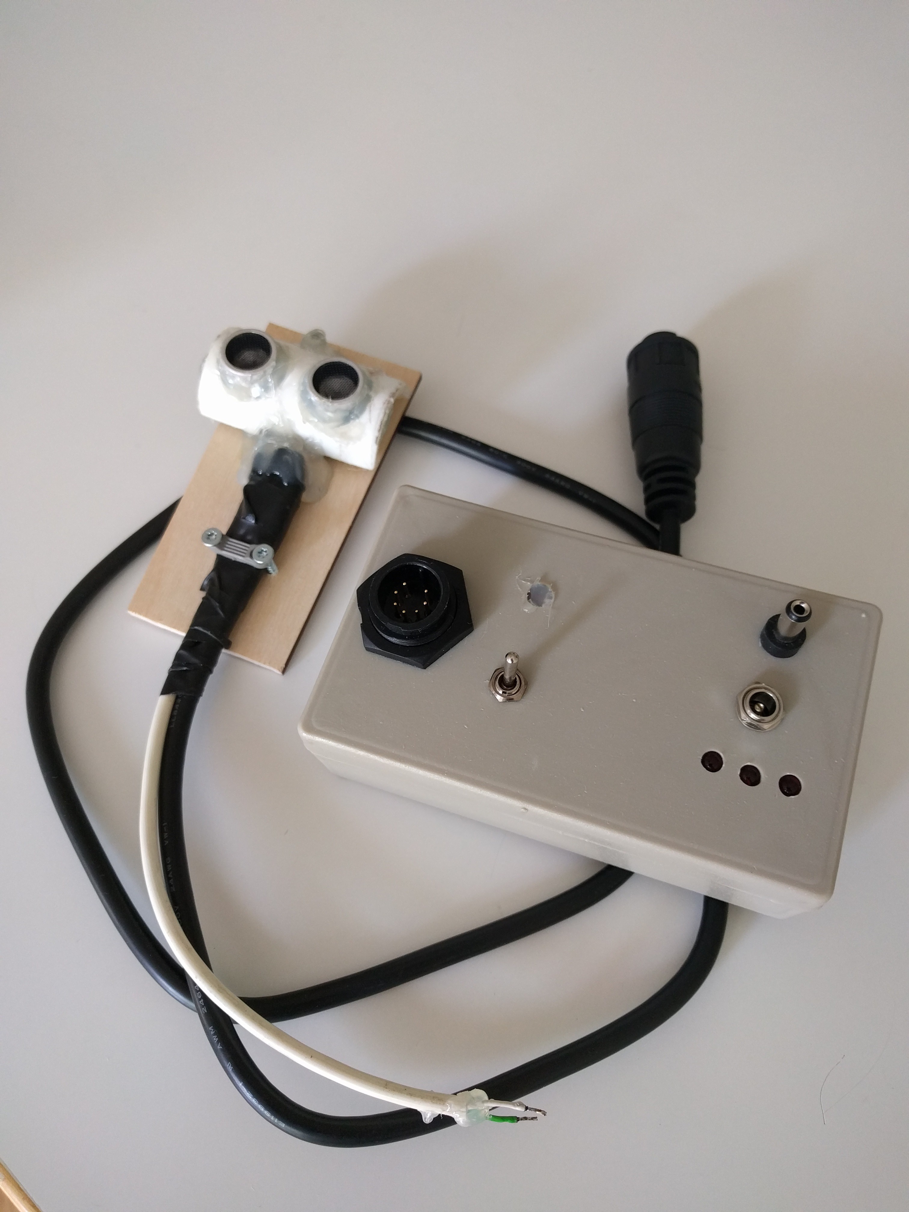
And here is the case. It has three leds - power, esp alive, and pump off (=inverted due NPN transistor). The case is too small, naturally, but it seems to be pretty firm when stuffed down. The nice looking connector is from dumpster diving. You can also see the professional looking ;) universal glue casing i made for the HC-SR04 ultrasound. I though it would be good to have some protection there since its going to hang over the water container. The switch is "manual on" - a switch to force the pump on for reason or another.
Now, back to code.
Discussions
Become a Hackaday.io Member
Create an account to leave a comment. Already have an account? Log In.