With all the previous discussion done, the motor mount is largely specified for us. It has a several deductive requirements. The motor mount must:
- Drive front wheel
- Allow steering adjustments (and so be mounted to the axle)
- Gracefully handle large momentary torque and vibration
- Accommodate a 185mm diameter drive pulley
- Accommodate a 50mm brushless motor
There are also a few requirements that follow to make the design robust:
- Accommodate a 35mm idler pulley to assure adequate belt wrap around the small 14 tooth drive pulley
- Allow for reasonable cable management
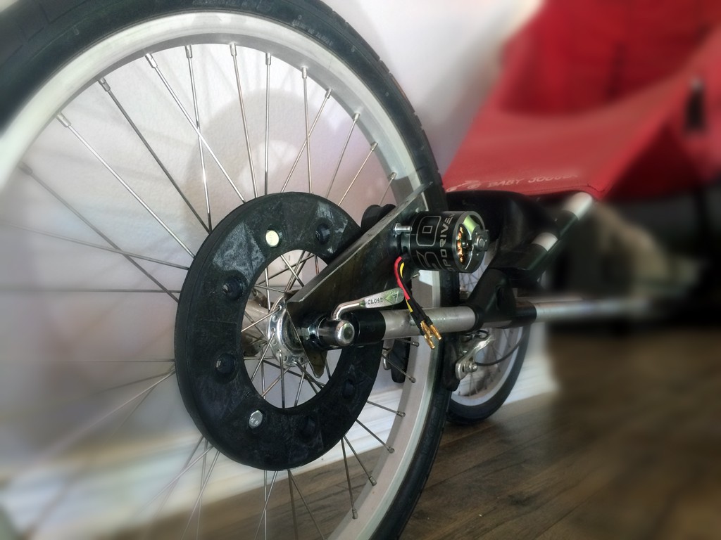
- Place the motor behind the front wheel to protect it from accidental bumps
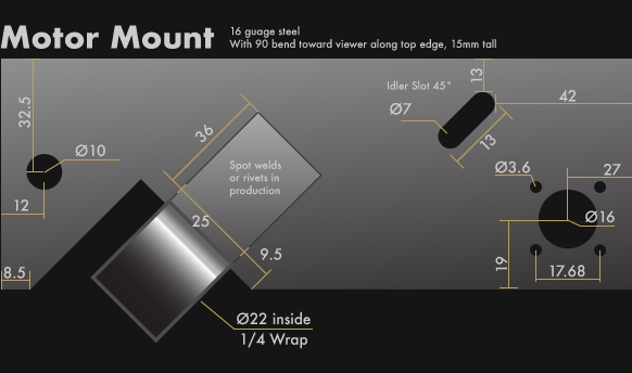
In order to not interfere with the front wheel mounting tubes, we need the motor mount to be rather skinny, but not bend. We can accomplish this by using 16GA steel with a reenforcing bend at the top. This design could be stamped in one operation, lending to cheap manufacturing.
This is actually the second iteration of the mount. Testing so far has shown almost no belt slip even with high transient torques (when a PID value may have been typo'd) and low static drag when the motor is off.
Prototype
Discussions
Become a Hackaday.io Member
Create an account to leave a comment. Already have an account? Log In.