 Pavel
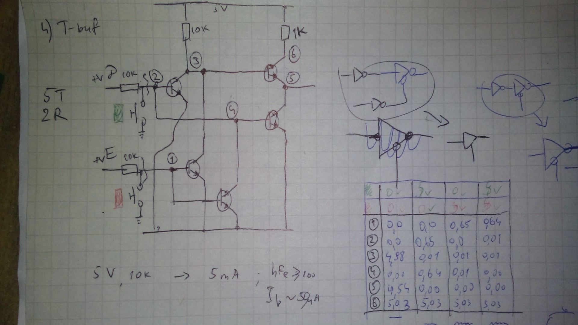
PavelAfter some tinkering, trial and error with breadboard, I arrived at seemengly good schematics for the t-buffer, using 5 npn bjts and two resistors. This turns out to be invertor with active-low enable, so it have to have inverted input. I figure, for saving slightly on components, I will use it as is, and connect its input to inverted out of flip-flop or latch.
This variant's HIGH output is one diode drop lower than positive rail, but I think, it will be acceptable for driving my dtl gates.
Here is the schematics with measured voltages in table:
Discussions
Become a Hackaday.io Member
Create an account to leave a comment. Already have an account? Log In.