 Pavel
PavelAs the first board is complete, now it is time to test if it works as a whole.
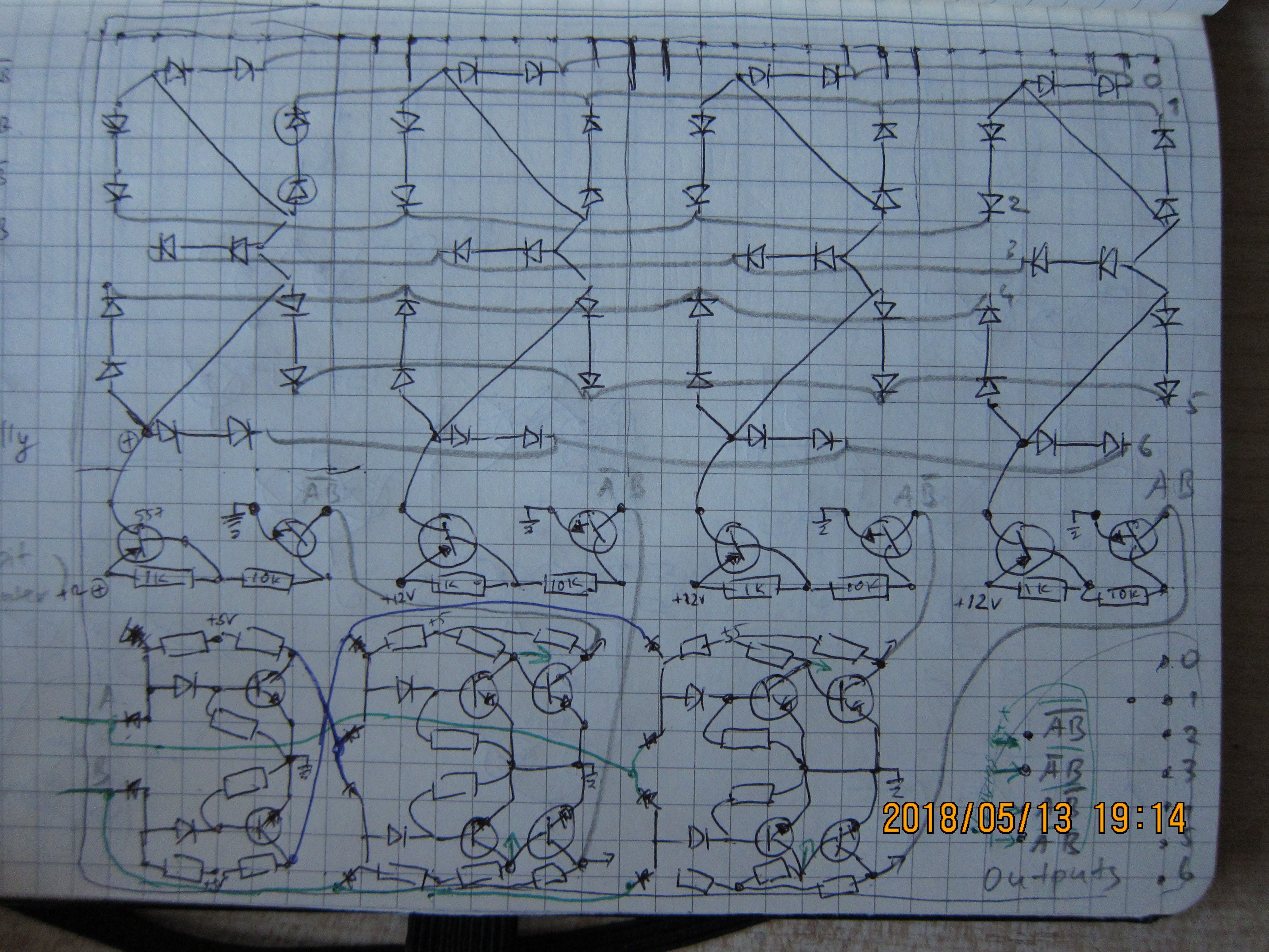
For start, for those who want to know, there is schematic (with all components pictured how they are placed on the board):
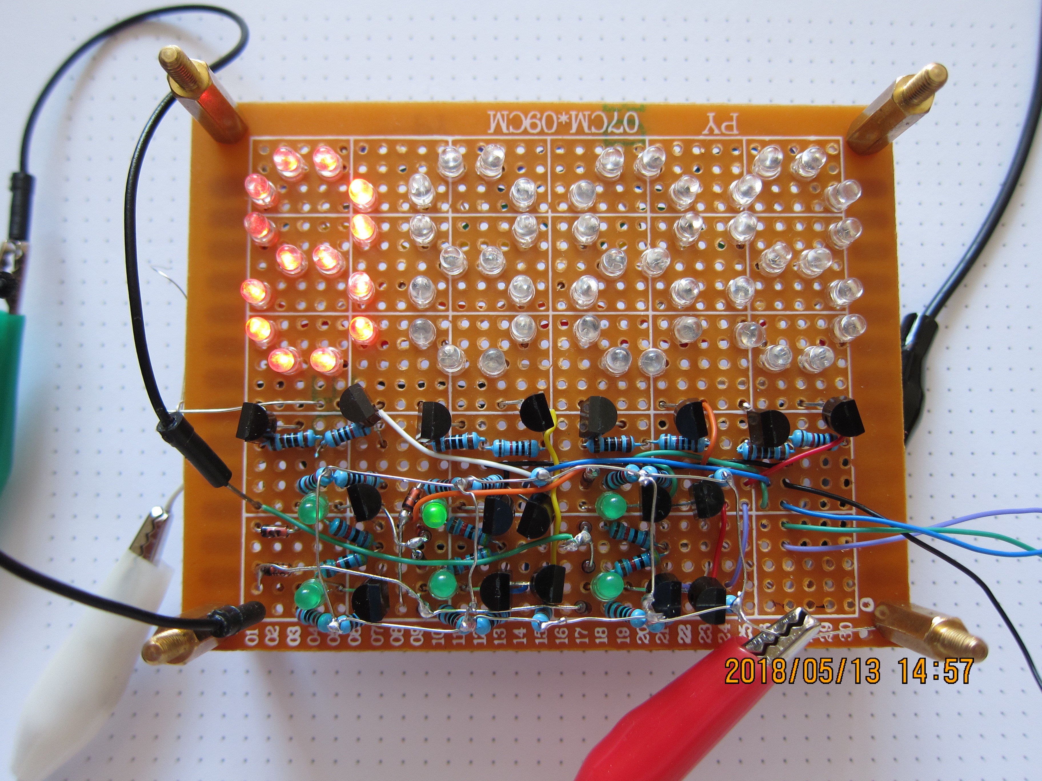
For test, to see all segments lit, their outputs were connected together and through 50 Ohm resistor to ground.
Testing with both inputs of 2-to-4 decoder connected to ground (black wires at the left side):
First input at ground, second floating (same effect as if it connected to high through resistor):
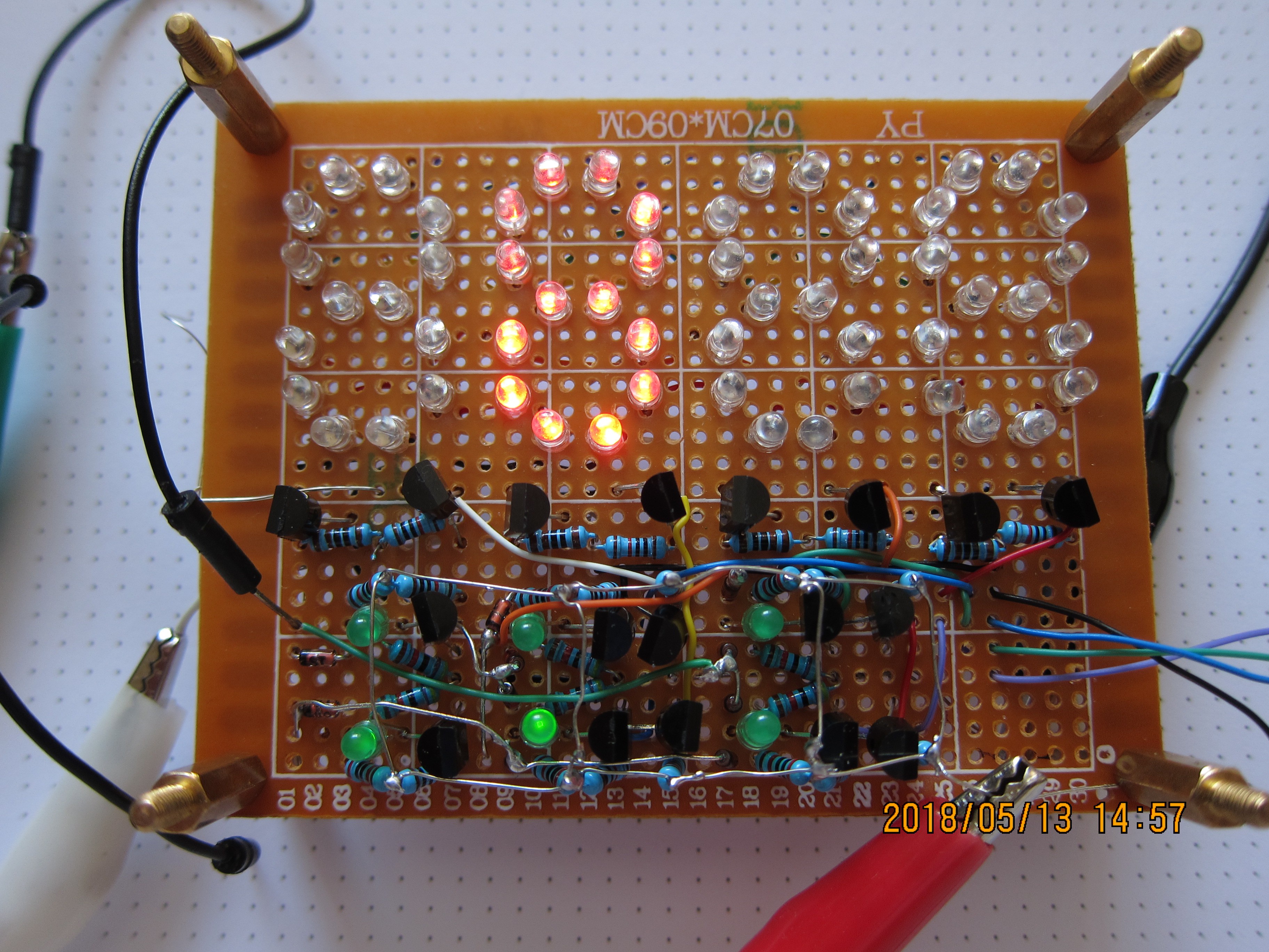
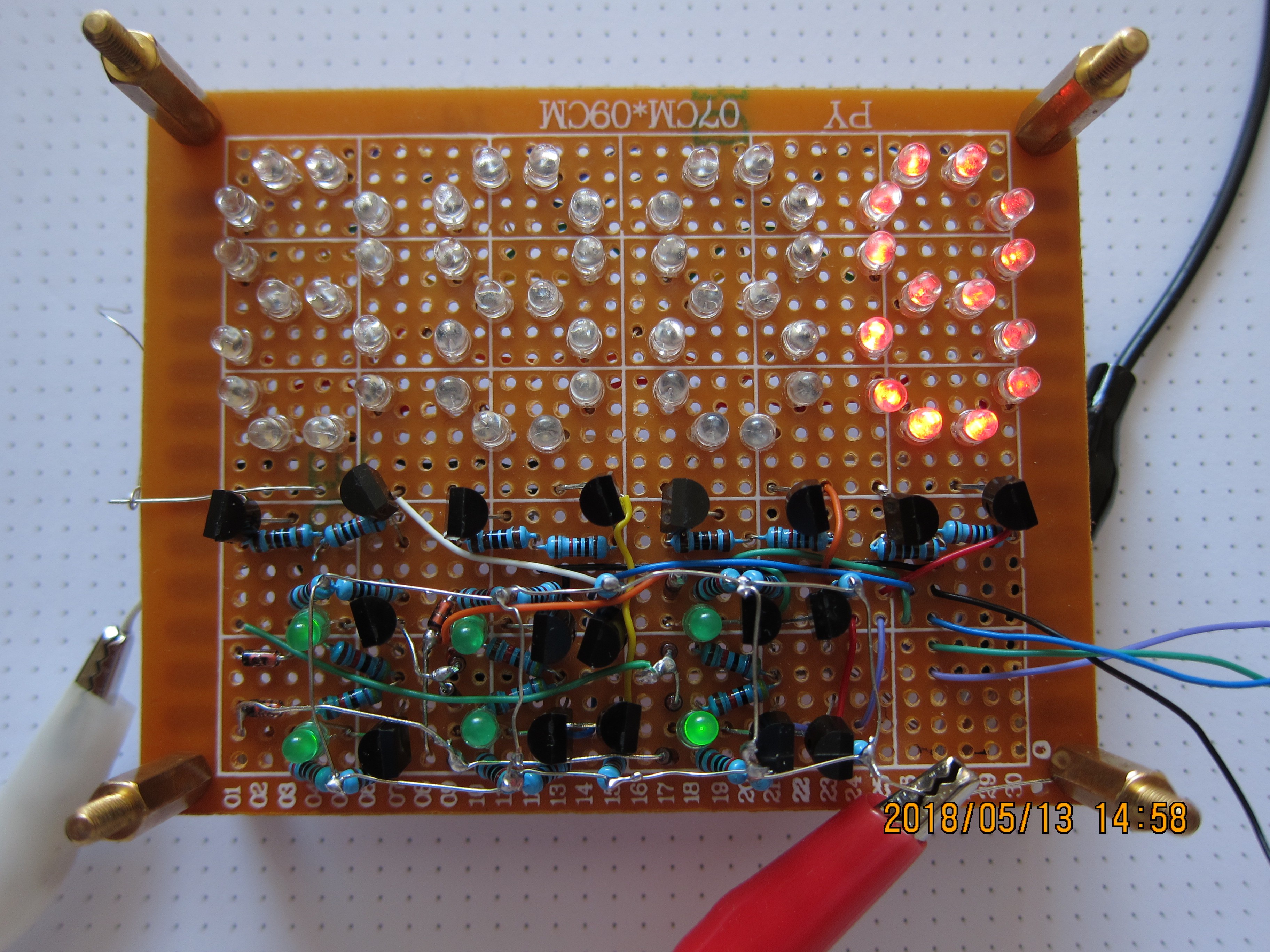
First input floating, second at ground:
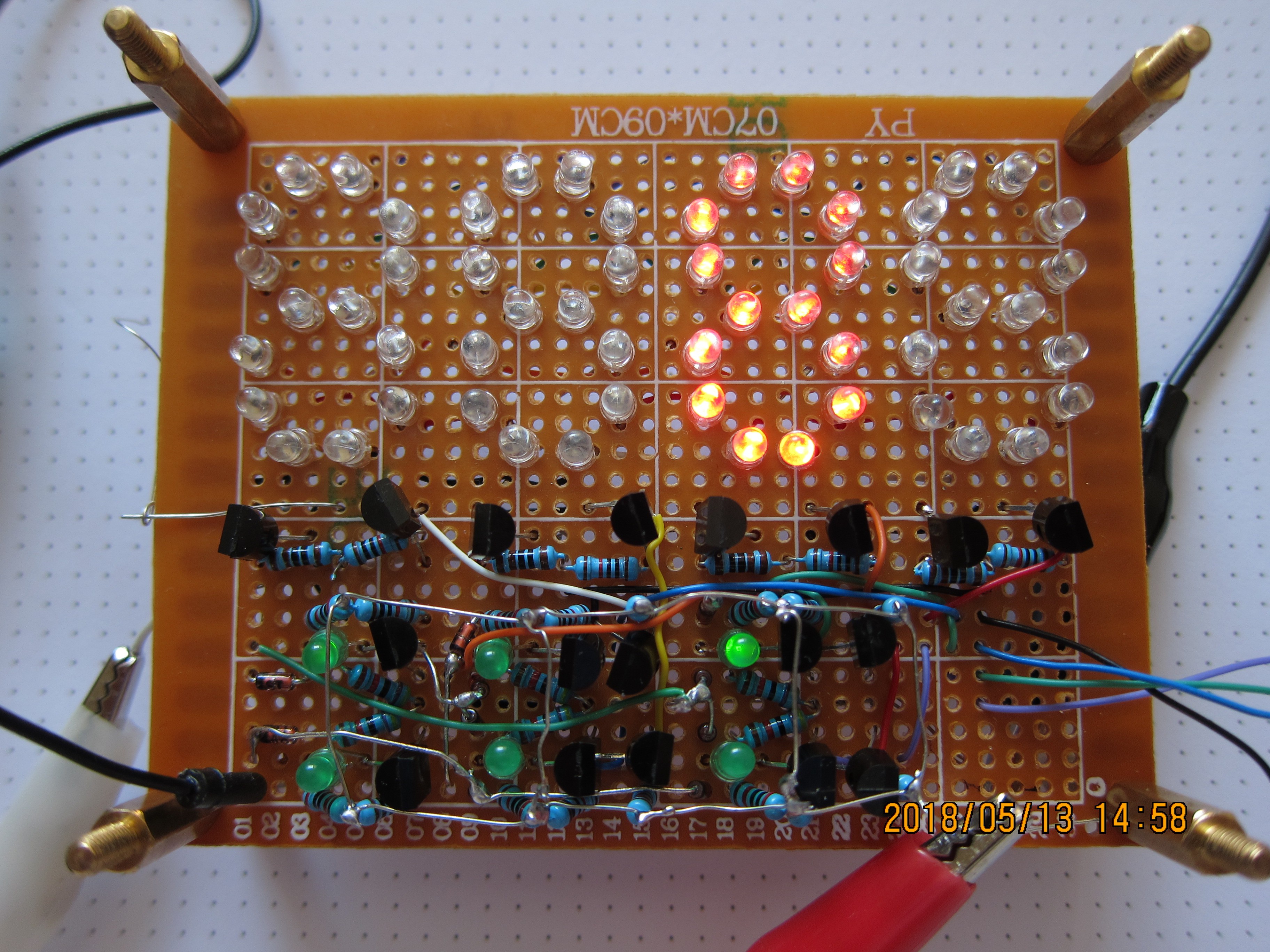
Both inputs floating:
Test was done with 7.5V.
Part count:
Red LEDs:_____________56 pcs
Green LEDs:____________6 pcs
1 kOhm resistors:__________4 pcs
10 kOhm resistors:________14 pcs
20 kOhm resistors:________6 pcs
47 kOhm resistors:________6 pcs
BC557 transistors (pnp):____4 pcs
N2222A transistors (npn):__14 pcs
-----------------------------------------------
total: 110 parts
+ some wires
+ 7x9 cm perfboard
I think, this constitutes sucsessfull build of first board.
Now, there are other boards to build: 16-to4 multiplexor (for breaking 16 bit word to 4 nibbles in succession), 4-to-16 decoder, 16-to-7 encoder for digits and clock/2-bit counter (for driving the whole thing at fast rate, so all four digits are seen to be lit simultaneously).
Discussions
Become a Hackaday.io Member
Create an account to leave a comment. Already have an account? Log In.