Pavel
Pavel-
Start of proper assembly
05/22/2017 at 05:22 • 0 commentsFinally I figured out powering scheme for segment and can start assembling the thing. For logic I will still use 5 volts, but for segments it will be 9 volts. Here I found some advice for dealing with powering segments: https://electronics.stackexchange.com/questions/233157/driving-large-common-anode-7-seg-led-with-npn-transistor-and-arduino-worked-but. As of right now, the display area (digits) and its powering circuit is complete. Here is how it looks like:
![]()
-
Prototype digit
05/10/2017 at 05:27 • 0 commentsThis weekend I made a prototype digit unit with wiring for segments mostly as described in log entry #2.
![]()
![]()
Segment selection done with two-position switches, and digit select is done with push-button switch. In full-scale implementation instead of switches there will be logic gates.
From initial measurements of current flowing through segments I think there should be another powering scheme, because total current through all 7 segments only about twice as much as current flowing through one segment, when it is the only one selected. I suppose I should use different voltages for logic and for display. Also there have to be some adjustments to wiring to accommodate the changes.
-
Tri-state buffer with bipolar npn transistors
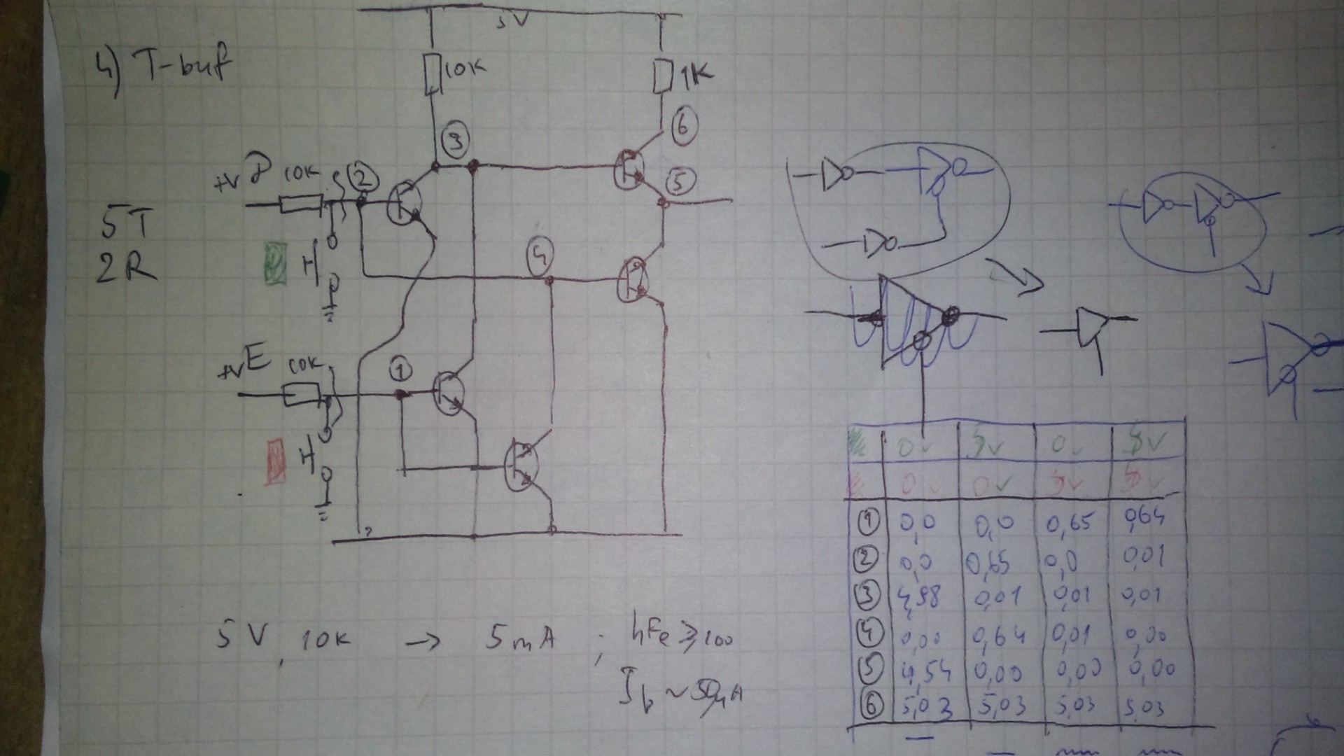
05/02/2017 at 05:09 • 0 commentsAfter some tinkering, trial and error with breadboard, I arrived at seemengly good schematics for the t-buffer, using 5 npn bjts and two resistors. This turns out to be invertor with active-low enable, so it have to have inverted input. I figure, for saving slightly on components, I will use it as is, and connect its input to inverted out of flip-flop or latch.
This variant's HIGH output is one diode drop lower than positive rail, but I think, it will be acceptable for driving my dtl gates.
Here is the schematics with measured voltages in table:
![]()
-
Driving the LEDs
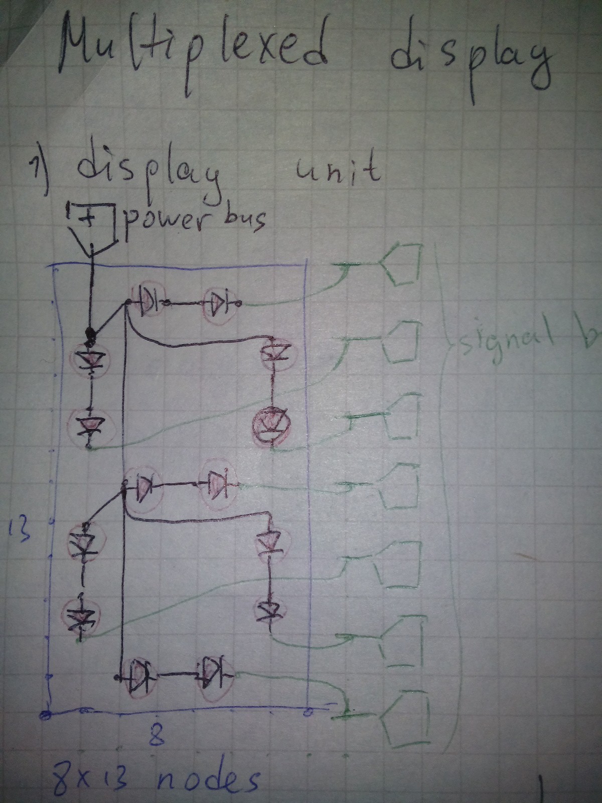
04/27/2017 at 04:42 • 0 commentsHere is planned layout of single digit:
![]()
All segments have common current source (coming from transistor emitter) and separate drains (collectors of other transistors).
After having several experiments on breadboard, I came to unexpected solution, where I do not need any resistors for LEDs to light properly.
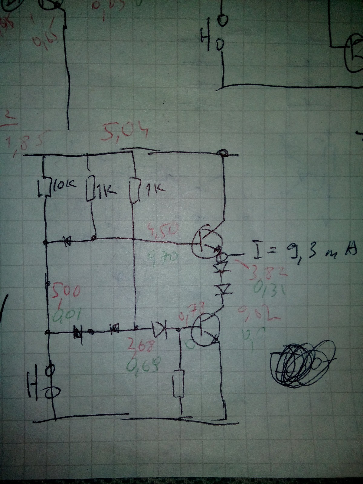
On the picture below is simplified circuit for driving single segment, with measured voltages and current through LEDs (lowermost resistor is 47 kOhm, the LED at base of bottom transistor is Green).
![]()
I do not like this solution, because LEDs are seem unprotected without resistor in series, but somehow it works. Also there seem to be that almost half of all current supplied by top transistor is coming through its base. Is there some more robust solution? Any help will be appreciated, meanwhile, I'll experiment further.
-
Commencing the project
04/26/2017 at 07:22 • 0 commentsI have 10*22 cm perf boards, which are 78*34 holes, from which I estimate I can place 8 digits. Each digit would occupy a plot of 8*13 holes on board. Each segment will be done as 2 red LEDs in series, which will have forward drop of 3.7 volts, so, driving them from 5 volt supply might pose some challenge.
I envisioning this device as comprised from several parts:
1) 8 digits (obvious) made from 14 red LEDs each
2) enabler circuits, sourcing supply current to digits at the moments when they should light up
3) 3 bit counter with base frequency of at least 800 Hz with 3-to-8 decoder for addressing digits and their respective registers
4) 4-bit registers for each digit, connected to common bus through tri-state buffers
5) transcoder, the unit which should decode 4-bit binary number from common bus into the pattern of appropriate segments; also this unit will sink current from segment diodes
6) special registers: input data latch (4 bit) and address latch (3 bit), so one could input a digit in specified place
7) some other circuitry yet unknown.
Registers will be done as data latches made with dtl nand gates (all from discrete electronic components). Counter circuit will be made from dtl nand master-slave data flip-flops as ripple counter (the same circuit as was used in my "counter/clock" project.
For now, the biggest problem for me is the implementation of 3-state buffers with bjts. As of now, I still have no solution, and searching the internet turned out empty so far. Closest I found was open emitter circuit, but it can only source current ( pull up voltage) but can not sink (pull to ground).