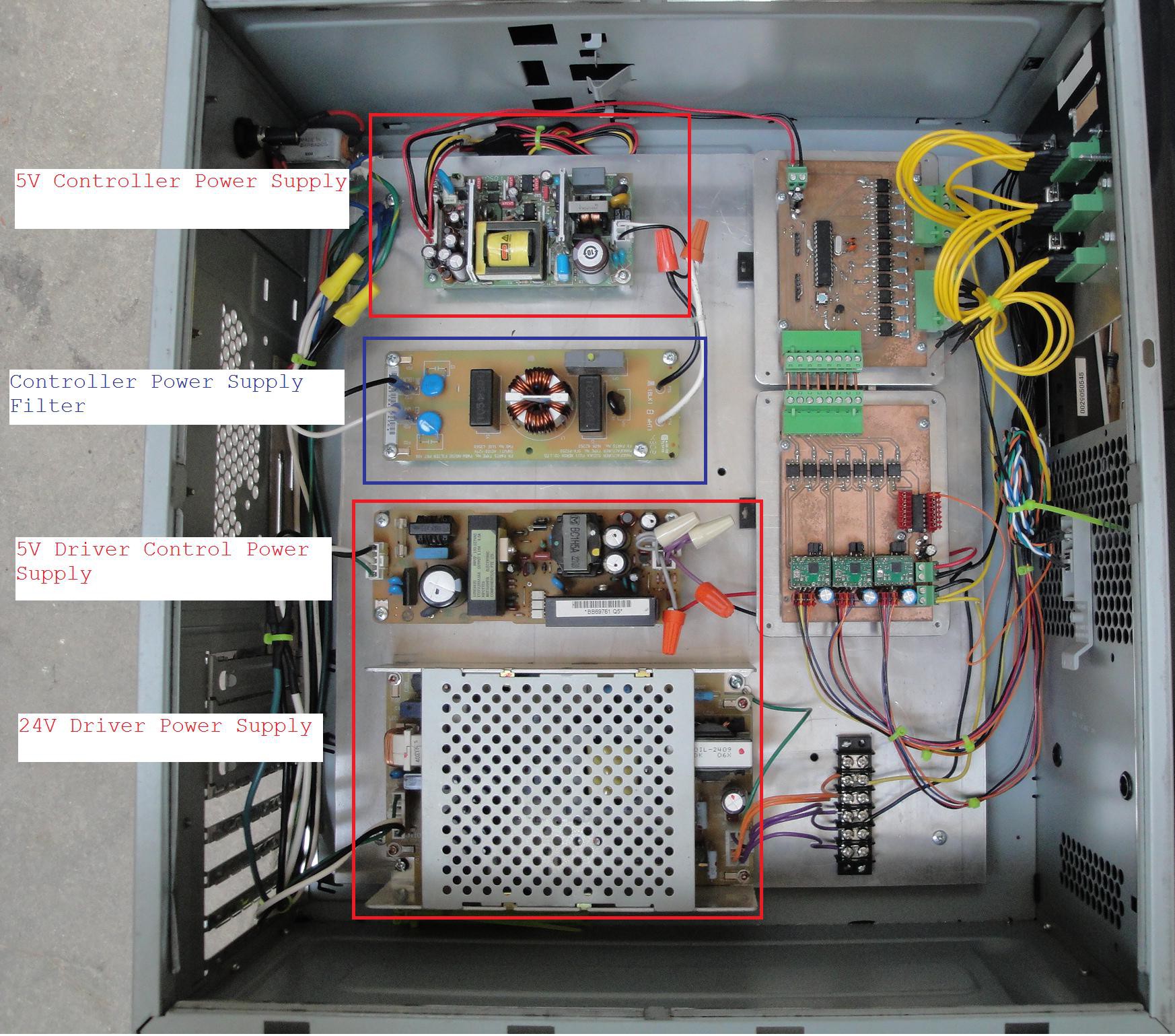
Now that the boards were complete, the boards could be wired into the box. The boards were designed to keep the 5V power supply voltages separate between the two boards. This required 2 separate 5V power supplies to feed the control voltages to the controller and driver board.
Below is a picture of the layout. The upper left hand corner board is the controller power supply. This is fed by filtered 120V line voltage.
Bottom left is the 5V and 24V power that is used on the driver board.
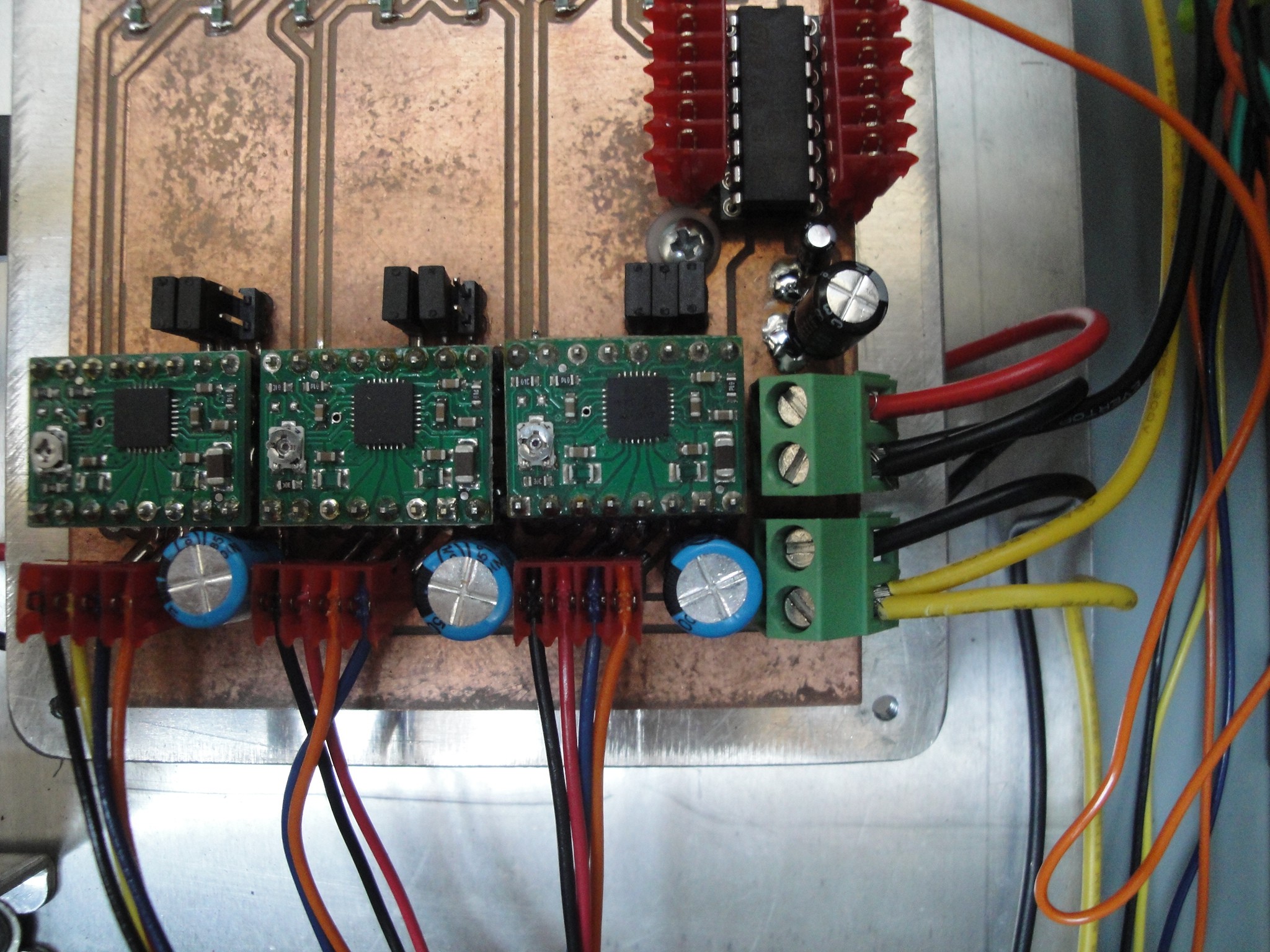
Next up was wiring the limits and joystick for minimal operation. I jumpered the Z positive limit and powered up the box. This led to the first problem. The motors were not powering up. Eventually diagnosing led to the 5V driver board power connector.
The two connectors to the right of the board is the 5V (upper green connector) and 24V (lower green connector) power supply inputs. The 5V supply power pin was not adequately soldered down. This was fixed by a quick solder.
The motors now powered up, y axis would home, but the x axis would not move. This was due to the program being changed to allow for easier creation of the boards. Once the program on the micro was updated to the correct version, the machine would now home in the x and y axis.
Currently the machine has the claw re installed and operational, the wiring run haphazardly and needing to be fastened, and the joystick not mounted to the machine. As far as I can tell the boards function correctly as all the limits work, the joystick controls the machine in the x and y axis, the claw closes when required and the machine homes correctly.
The next step is to clean up the machine and make it more presentable.


Discussions
Become a Hackaday.io Member
Create an account to leave a comment. Already have an account? Log In.