Close
0%
0%

Funky Light

"Funky Light" should improve theatre performances in schools, by giving teachers and students an easy to use tool to control the lighting.

Similar projects worth following
This is work in progress, so we would love to get your feedback about our Project.

First of all what should Funky Light be and how does it work?

Funky Light should be an easy to use tool that give teachers and students the opportunity to design the lighting of their theatre performances as easy as possible.

We got the Idea of Funky Light when we prepare theatre performances in our drama classes. We had a lot of Ideas for the lighting during the performance, but it was hard to control all of the different lighting scenarios by hand (we only had a crappy old Leprecon Console to control the lights). But since I am one of the geeks on my school, I decided to hack this stuff with a friend of mine and make it controllable by a PC. After a lot of research with an oscilloscope we discovered that we can control the lights with a simple DMX command.
So the Funky Light Project was born!

For more information on how Funky Light actually works read our detailed description.

With Funky Light we describe two different Layers, one of them is the server side and the other one is the client side. We want to design the server side independent from the client, so we could easily exchange the client for an off the shelf product (DIY didn’t work all the time in a school environment especially when the developers left the school).

The Server Side is quiet complex and should be the hub between the physical world (Lights) and the client, but with the addition that the server uses a common used communication protocol to talk to the client. In our case we choose OSC (Open Sound Protocol), because it is commonly used to control mixing tables. To build our server we used an Arduino Yun with a custom made Shield, you find more details in the Server section below.

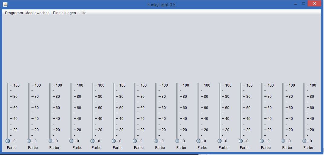
Besides the fact that you could use Funky Light with any Software that is capable of using the OSC protocol we start designing our own software that is specially build for this case. So we have an easy to use bundle that consists of the server as well as a client. We wrote a detailed description in the Client section below.

We already managed to build a prototype and tested it in the assembly hall of our school. We would love to get your opinion on our project so we can improve Funky Light.

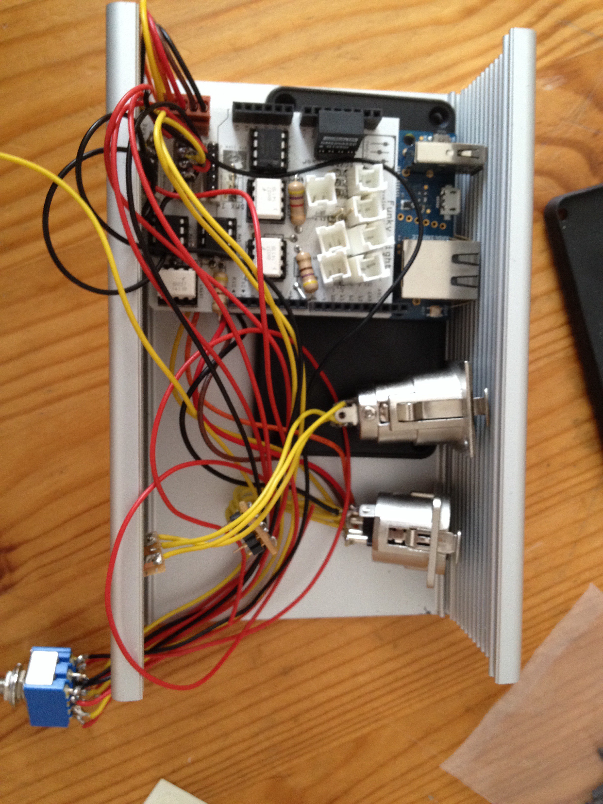
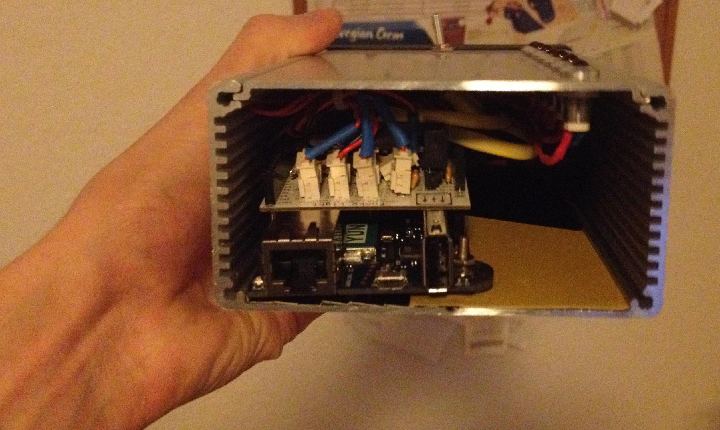
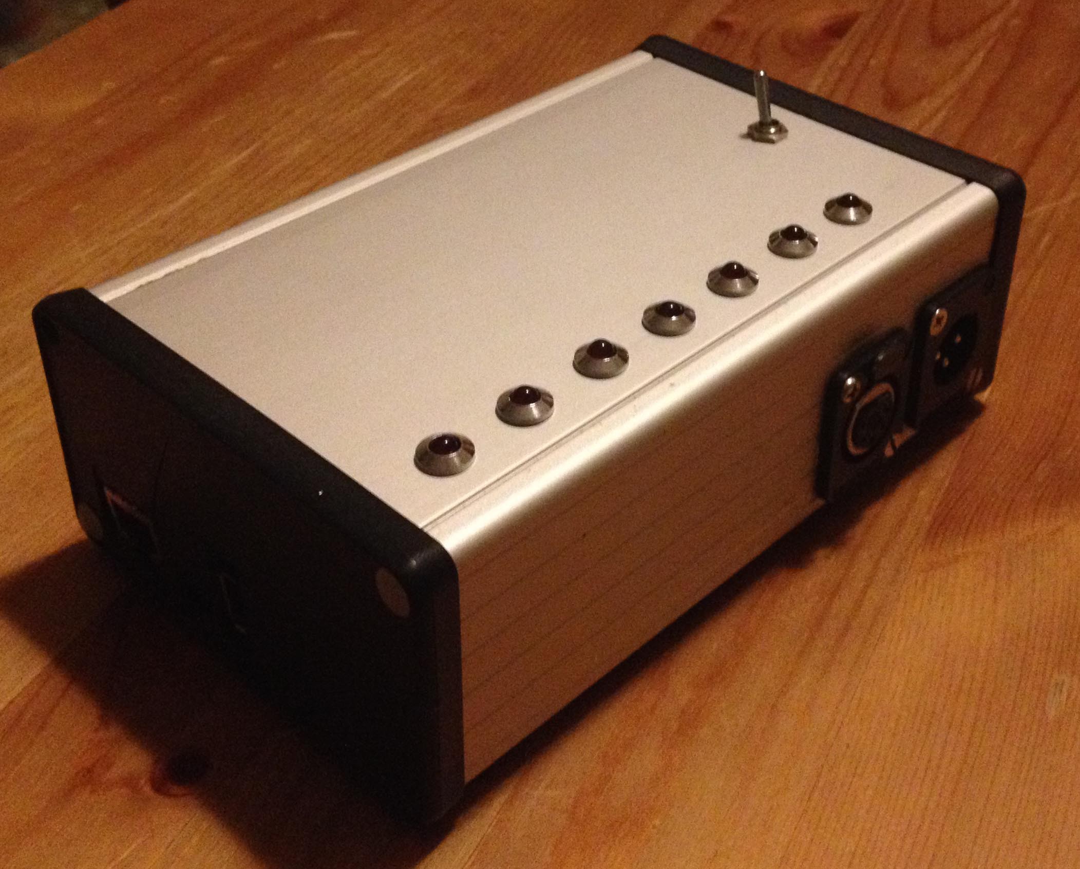
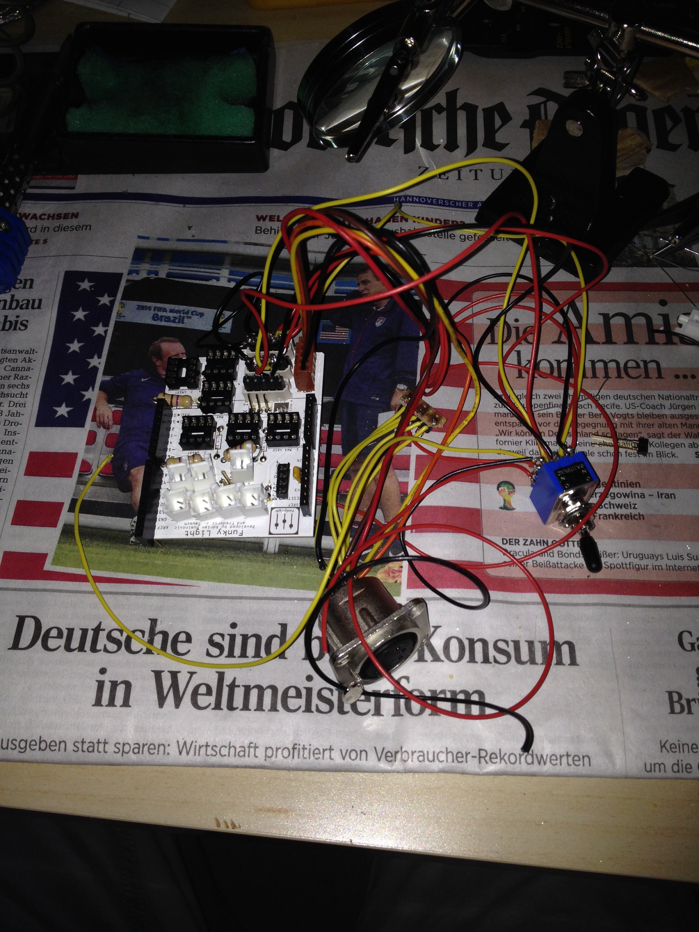
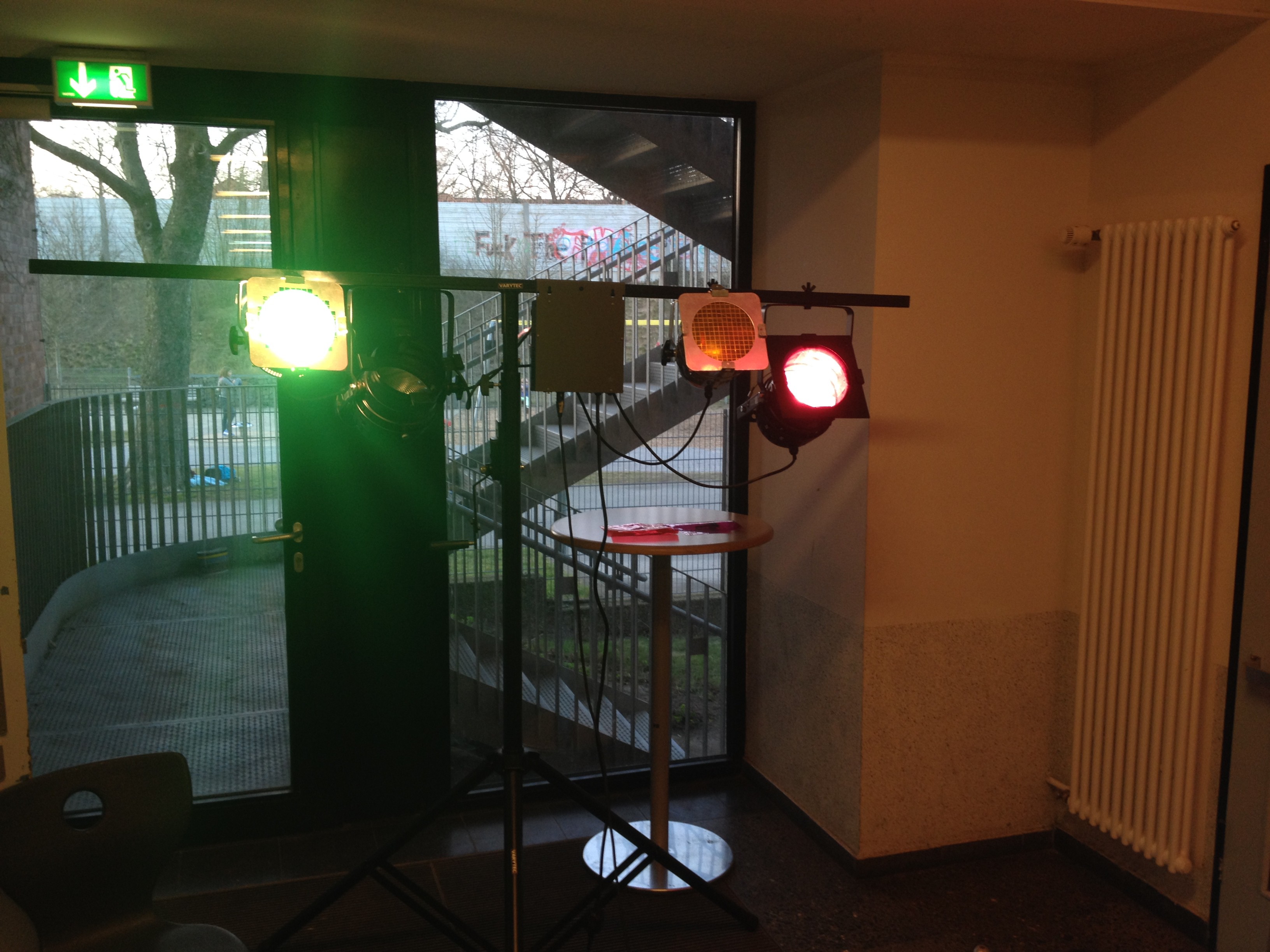
Our first prototype of the Funky Light Server

The Server Side of Funky Light

Okay let’s talk about the server side, first of all I want to give a short overview. The Hardware of Funky Light is based on an Arduino Yun with a custom made PCB that controls 3 DMX universes. Two of them are outputs and the third universe is used as an input form mixing consoles or whatever.

Before we describe the actual design of our hardware we want you to know why we use this type of setup, if you are not interested you can skip that part and continue reading in the Hardware section.

One of the first question that we had in mind was, how the client talks to the server. After a lot of research we decided for OSC, because it is a commonly used protocol in similar projects. And since every teacher and student should be able to control the whole system with their own device, we needed the server to support ethernet as well as wifi. At this point we started searching for a the right development hardware that supports wifi as well as ethernet in association to a microcontroller that should handle all the DMX stuff. The cheapest and easiest Hardware we found was the Arduino Yun, so we continued working with the Arduino Yun.

So why to outputs and one input universes, the main reason why we used to output universes isn’t that we actual need it, we will never have enough lights that need all the two times 512 channels. Moreover it is the fact, that most schools use the 5 pin DMX cables, which are capable of two DMX channels, so they can easily distinguish between audio cables and data cables. So why not supporting two output universes.

Additionally we build in a safety feature, because complex hardware and software always fails when it matters. The safety feature is a switch that defines the source of the output signal, you could choose between the generated signal from the Arduino and the signal from the input universe, so we can ensure that the lighting control never fails. 

The Hardware

Okay let’s start digging deep into the Hardware, especially the Arduino shield.

The Hardware of the server side consist of several parts:

  • A Linux operating system that runs some python scripts to manage all the clients and bumping messages around. For that we used the Linino of the Arduino Yun.
  • A Microcontroller manages the he whole DMX data output, for that we use the microcontroller of the Arduino Yun.
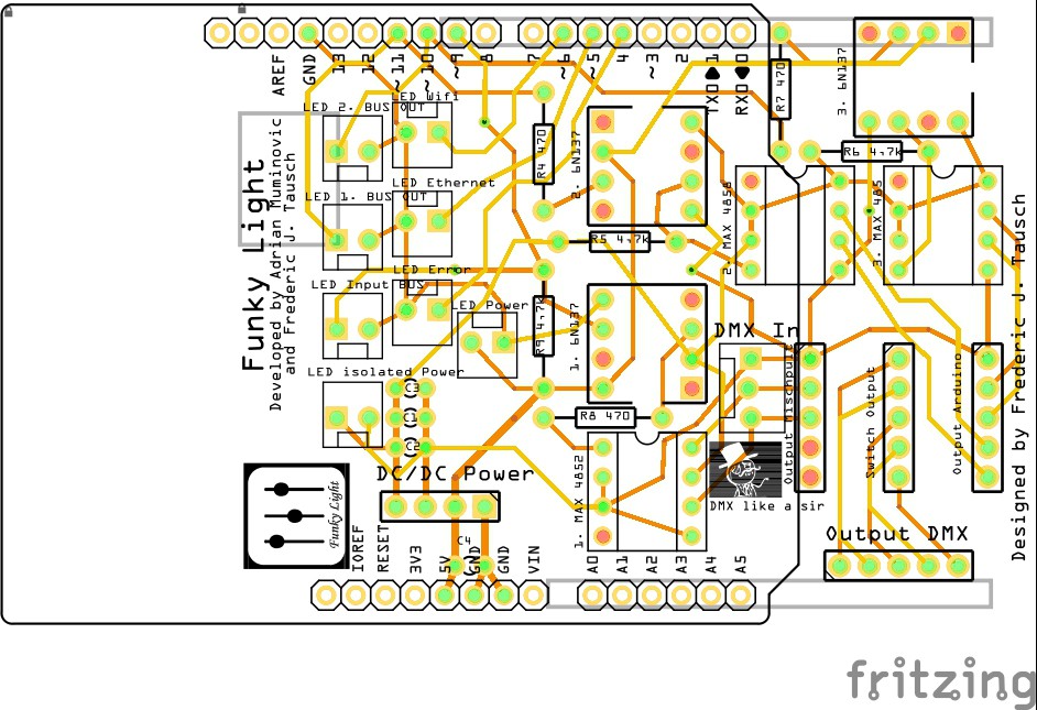
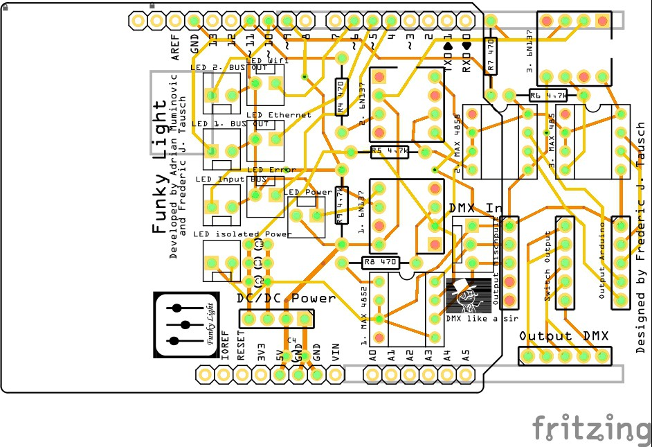
  • A custom Arduino shield separates the circuit of the Arduino Yun from the DMX signals with some Optocouplers. Additional it does all the additional work to get from a Single Bus to the DMX pinout. The schematicsfile are here (The Geber Files).

Arduino Shield

You could find a detailed overview of the whole structure in the nice diagram at the end of the detailed description.

The...

Read more »

  • 1 × Arduino Yun The Arduino Yun is a microcontroller board based on the ATmega32u4 and the Atheros AR9331, that runs a special version of OpenWrt
  • 1 × Custom made PCB
  • 3 × Opto-isolator IC, Fairchild, 6N137M
  • 1 × DC 5.5V / DC 5V converter (Galvanic isolator) Murata DC/DC-Wandler (NME0505SC)
  • 3 × Line Transeiver MAX485CPA+

View all 12 components

  • Back from the death

    Langhalsdino04/07/2015 at 20:24 0 comments

    Dear fellow readers,

    we are so sorry that we did not update our page during the last month, even if a lot happened during the time. We still pursue our goal of an easy to use tool to control the lighting for students and teachers.
    Sadly, we have to study a lot for our final examination, so there is not much time keep up with the project on hackaday.io . After our graduation, we will continue our project and update the whole thing!
    If you still want know a little bit more and can speak German or a satisfied with google translate visit http://funkylight.thebrokenprojects.de/ for more and fresher information (we done this page for a german competition).

    Ohh and I want to mention, that FunkyLight attended the German competition "Jugend forscht", a national renowned science competition ( http://en.wikipedia.org/wiki/Jugend_forscht ). Furthermore, we are now part of the finalists and attend the last stage of Jugend forscht. Fingers crossed.

    Langhalsdino

  • It has been quite some time, but we are back!

    Langhalsdino11/05/2014 at 20:47 0 comments

    Dear Hackers, Makers and everyone who will read this project log,

    we are back from the scary grounds of exams and other school stuff that invades your free time.

    We finally managed it to build a crappy, but still quite solid case for the Funky Light hardware. In the next time we will deploy the hardware in assembly hall of our school and work more closely on the software.


    .


    .
    We are planning to post a short update video of the working prototype of Funky Light.
    The next step will be to publish the software and we will publish the source code too.

    Langhalsdino :)

  • Second try :(

    Langhalsdino09/11/2014 at 22:02 0 comments

    This should only be a short update on our project.

    We got some bad news for you :(

    In the past days, our prototype got stolen, so it took us some time to get all the parts for a new run. But now the time has come for a new run, we soldered all the necessary and important parts on the board to begin a new testing phase. Hopefully we can show you some incredible pictures of the working prototype in the next days.

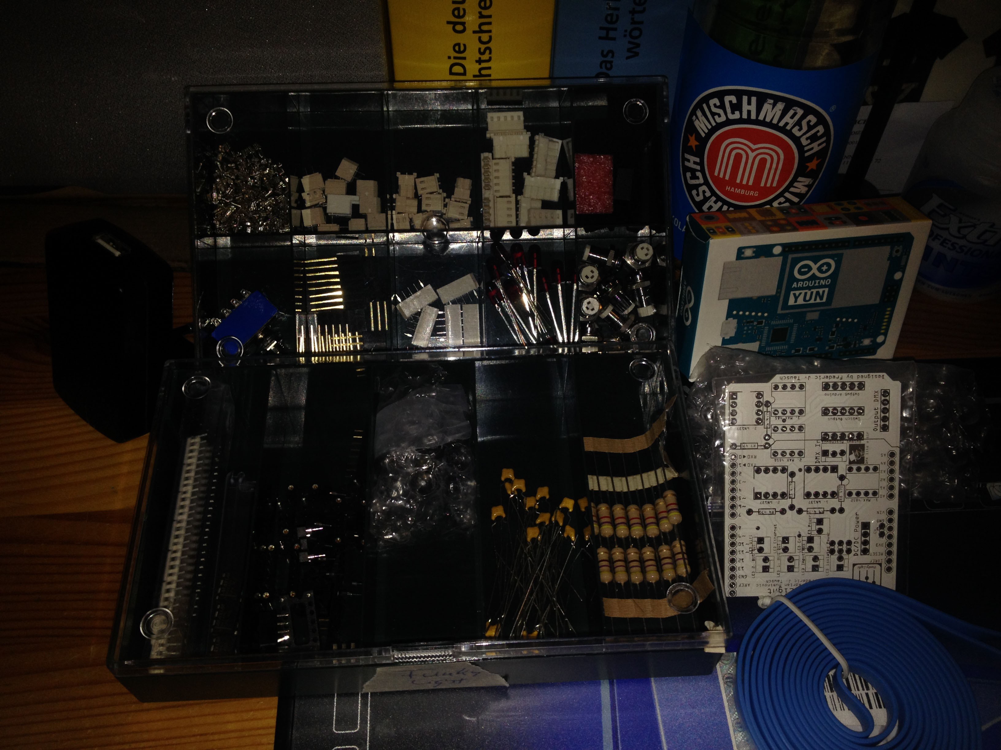
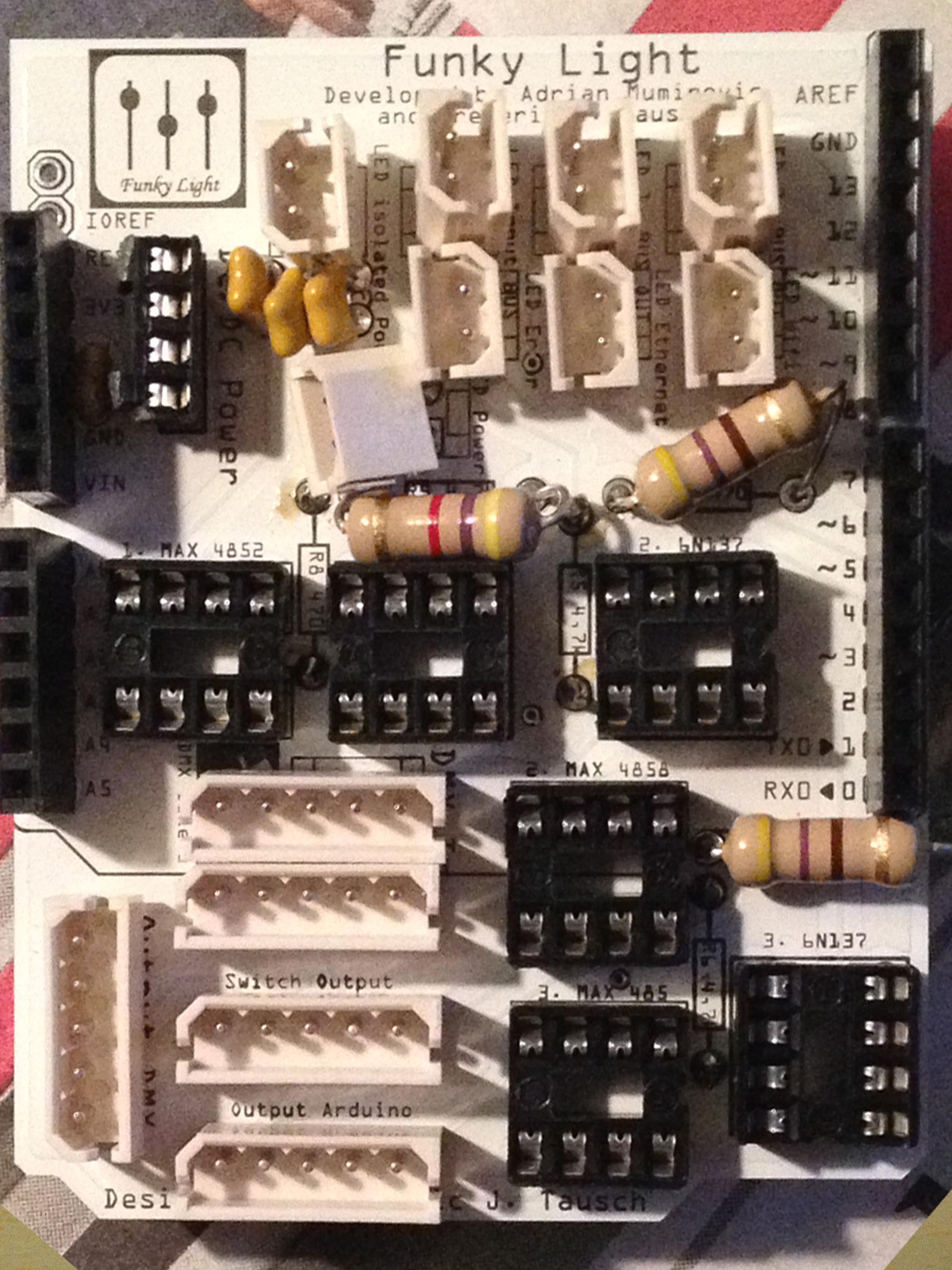
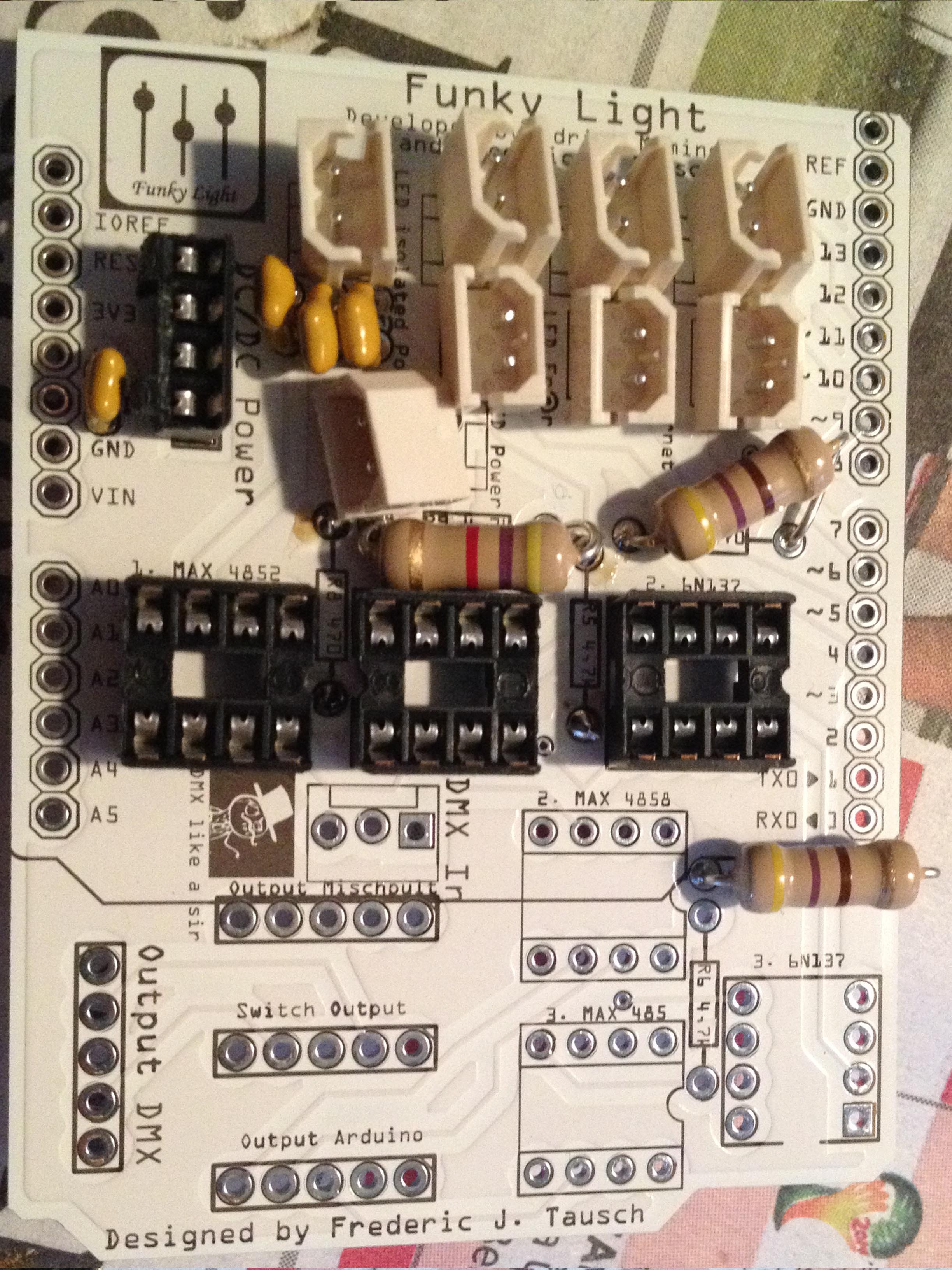
    To make the time of waiting more likable we got some nice pictures of our unfinished Prototype for you.

    ----UPDATE -----

    Ohh, what is that? We found a video that looks like it is a Video from the testing phase of Funky Light.

    ----UPDATE------

    Sincerely Langhalsdino

  • Testing the finished PCB

    Langhalsdino08/21/2014 at 01:57 0 comments

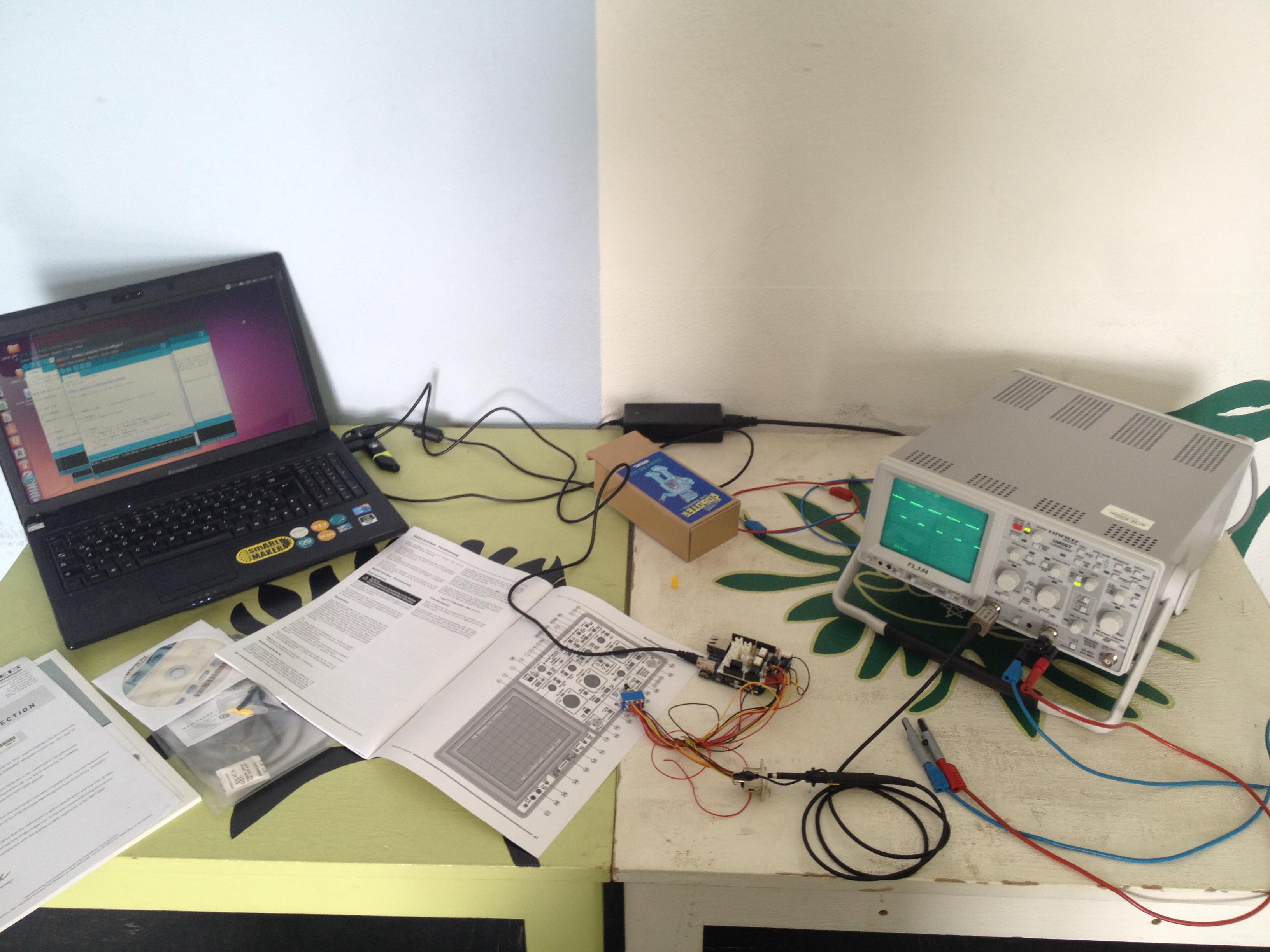
    I got the oscilloscope of the physics department to run some tests on the circuit board and the results are great.

    The signal on the oscilloscope definitely shows the characteristics of the photodiode from the Opto-isolator, but that was no problem for our test equipment, it lights up again.

    Since the summer holidays begin in the next day, we finished with the prototype of the hardware and went over to the software side. Hopefully the software will have a lot more features to test at the end of the summer break.

    With great regards, Langhalsdino 

  • Assemble the new PCB

    Langhalsdino08/21/2014 at 01:50 0 comments

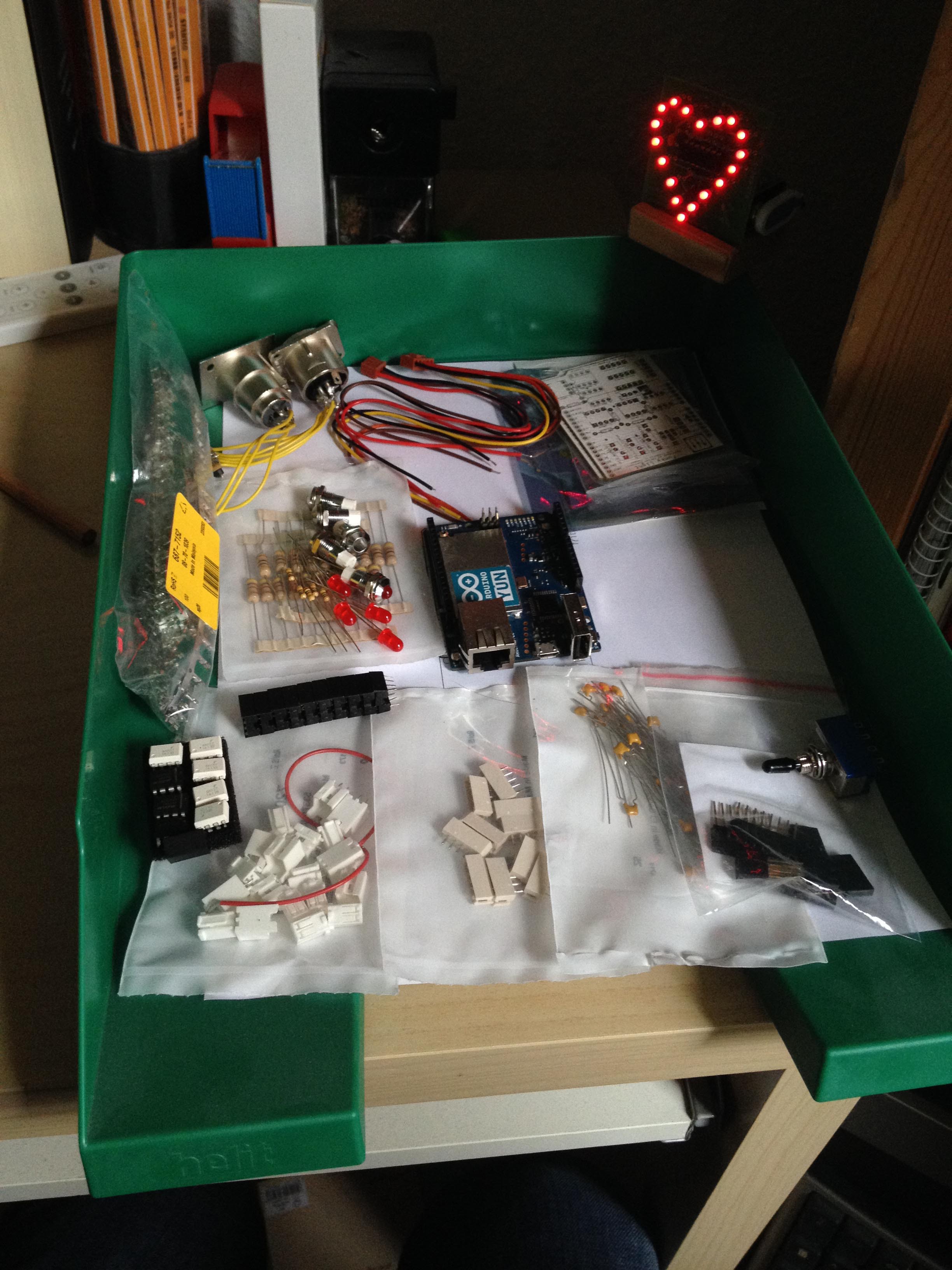
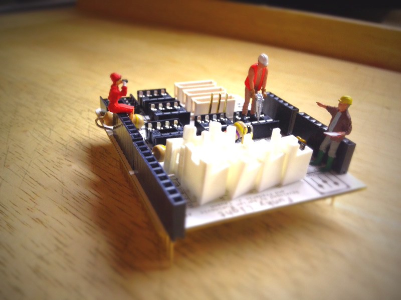
    Hey, the new PCB arrived as well as the new parts, let’s start soldering.

    I uploaded some nice pictures of the new parts, and my soldering work :)

    Hopefully you enjoy my last picture.

    After I finished soldering I plane the testing phase of the circuit board for the next day at school. Hopefully I can lent me the oscilloscope from the physics department.

    Your Langhalsdino.

  • Rethinking the circuit

    Langhalsdino08/21/2014 at 01:39 0 comments

    Okay, after several test we noticed that it would be great to separate the current/circuits of the Arduino Yun and the DMX Signal, so we rethink the whole circuit.

    We stated using a Galvanic isolator and some Opto-isolators, hopefully that will work out.

    Here is a picture of the new PCB Layout. The Layout of the PCB now has different areas, that represent different tasks, for example the isolation areas or the area of the Transceivers. This time we will order the PCB, so the second version will look much more professional.

    Ohh and we ordered new parts for the PCB , the List of Components got updated as well.

    See you next time, Langhalsdino.

  • Etching the circuit

    Langhalsdino08/21/2014 at 01:29 0 comments

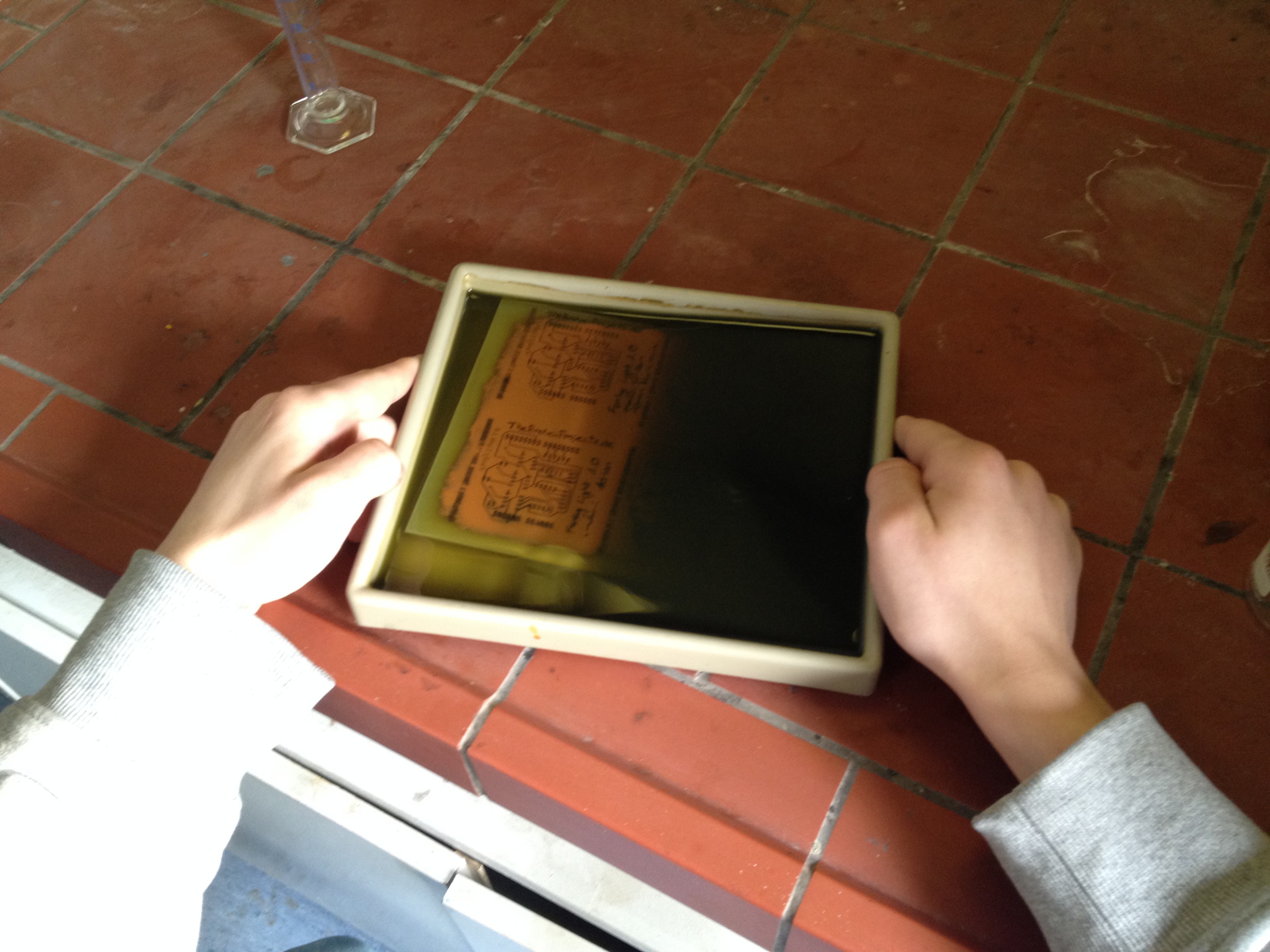
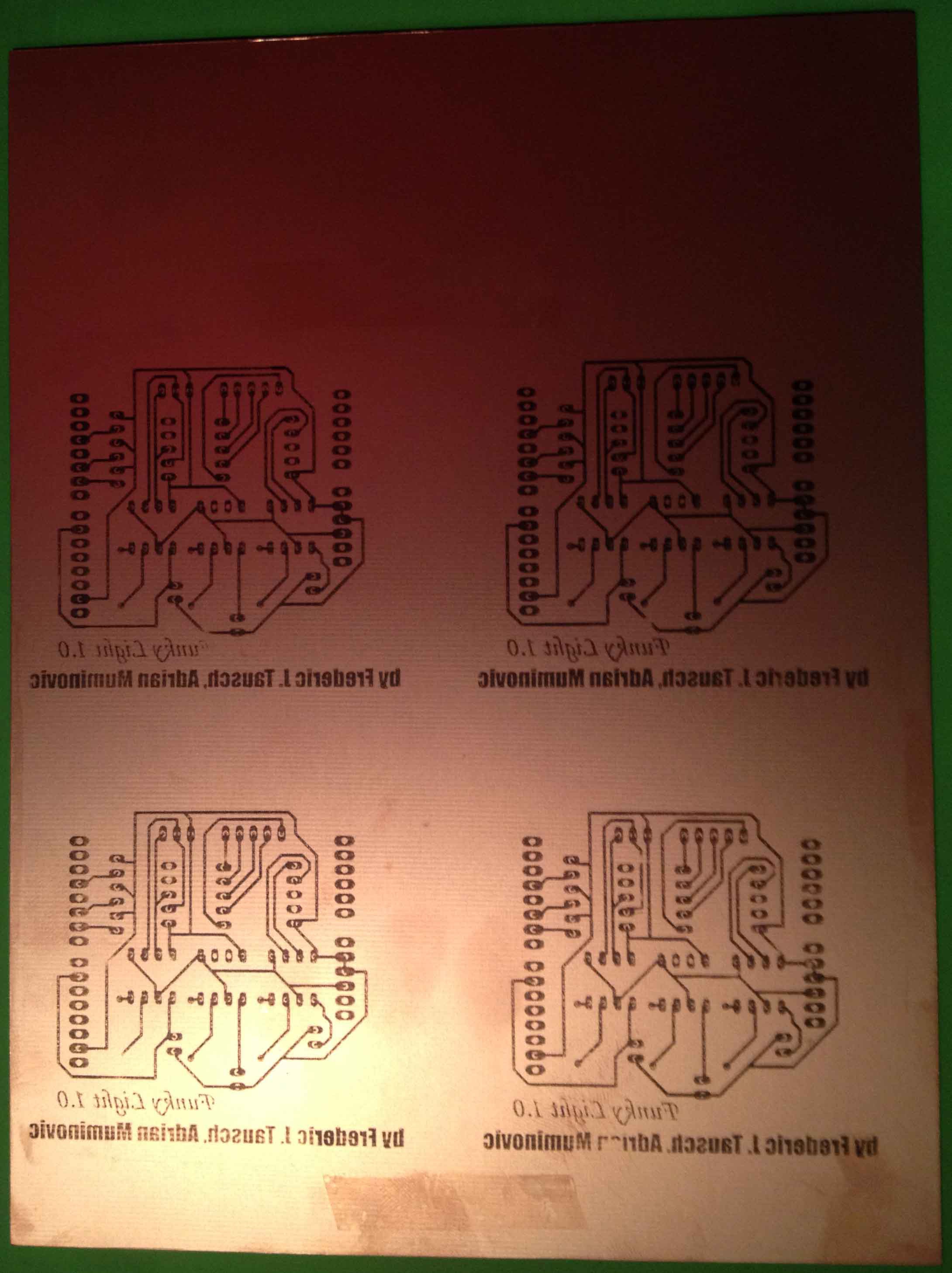
    This time we started etching our first circuit board by our self, fingers crossed. Let’s see how it ends.

    Etching the circuit

    For this one we used a lot of acid, but it still took its time.

    Here is another picture of the etched PCB, did not turned out that well. But it will work for the first prototype.

    Sincerely Langhalsdino

  • Breadboarding

    Langhalsdino08/21/2014 at 01:23 0 comments

    Good morning, this is my first project log.

    We started working on the Hardware of Funky Light and develop the circuit, which connects the Arduino Yun to the Lights.

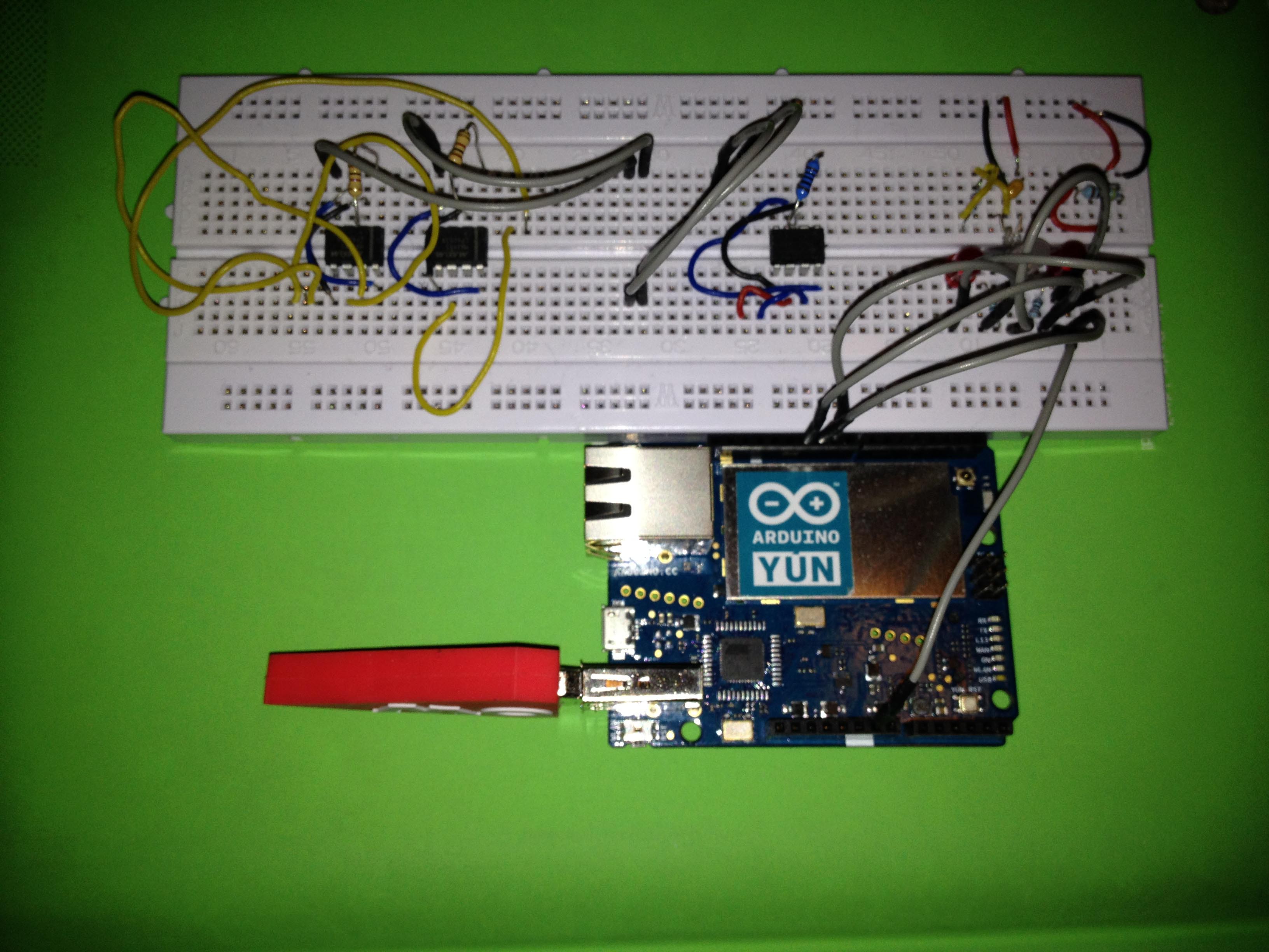
    Enjoy the cool Picture of the nice breadboard. 

    Breadboarding the circuit

    It’s not that fancy, because we only testing the Line Transceivers. But it works great, hopefully we got the OSC Software running in the next days.

    This is our test equipment, I hope you like the Funky Lights :)

    Have a nice day, your Langhalsdino.

View all 8 project logs

  • 1
    Step 1

    We are really sorry that this project is not that far, so that we could give detailed step-by step instructions. They will come, but it will take its time.

View all instructions

Enjoy this project?

Share

Discussions

Similar Projects

Does this project spark your interest?

Become a member to follow this project and never miss any updates