 Chris
ChrisAfter some time, here it is! These are the finalized Rev 1.5 schematics and pcbs!
I will start with the most exciting picture which is the pcb as it will be seen hopefully in real life (render from oshpark obviously).
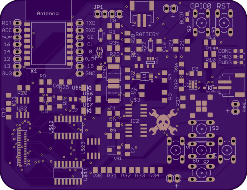
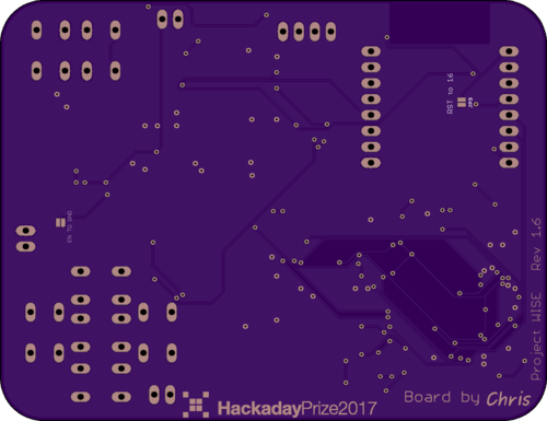
Overall the design isn't very complex and I choose mostly 1206 size smd components for easy hand soldering and hacking when things inevitably go wrong. In the next revision of the board I will probably move to 805 size components which will help lower the cost of the boards a bit.
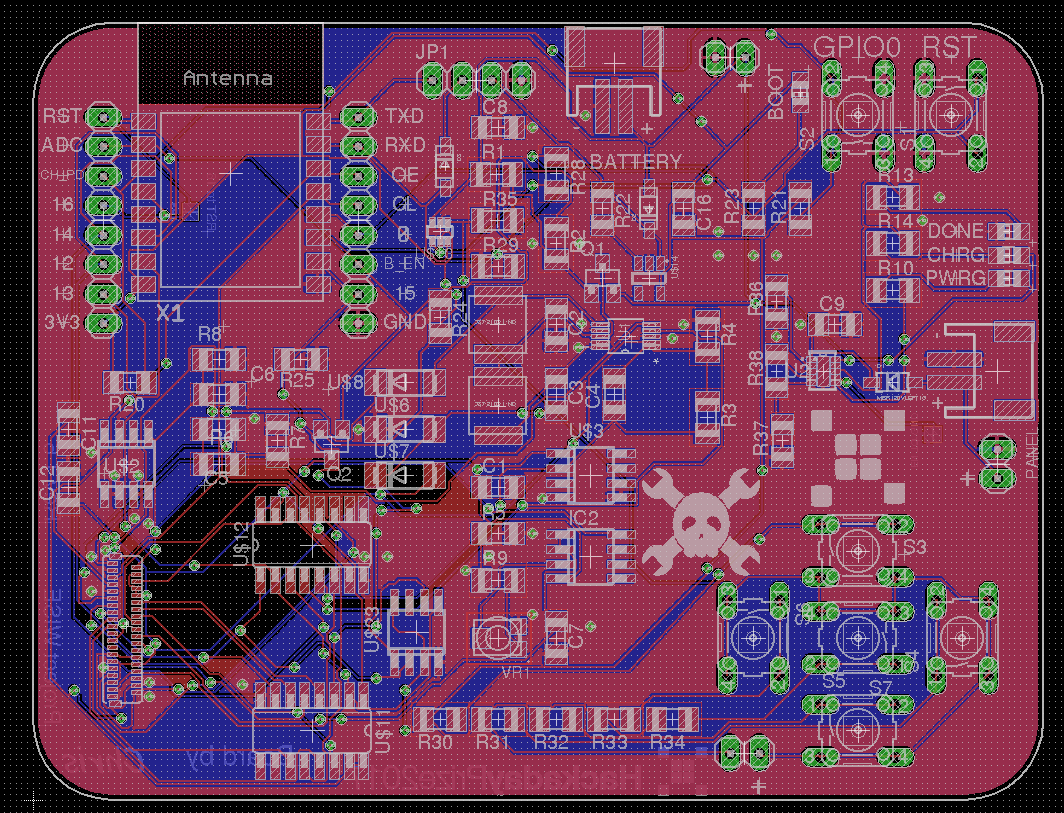
Below you can see what the pcb looks like in Eagle and it is pretty different from the first version I posted here.
The two biggest changes are the addition of a flash memory chip and the use of a different solar Li-Po charger. These can be seen in the schematics below. Other than a few different bug fixes the schematics between Rev 1 and Rev 1.5 are mostly unchanged.
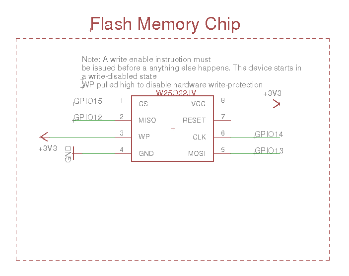
I selected a chip with only 32MB of storage to keep the cost down for now. I figure that this is still enough to hold a handful of books and will hopefully be easy enough to upgrade. I have never used flash memory so this will be a good learning experince for me.
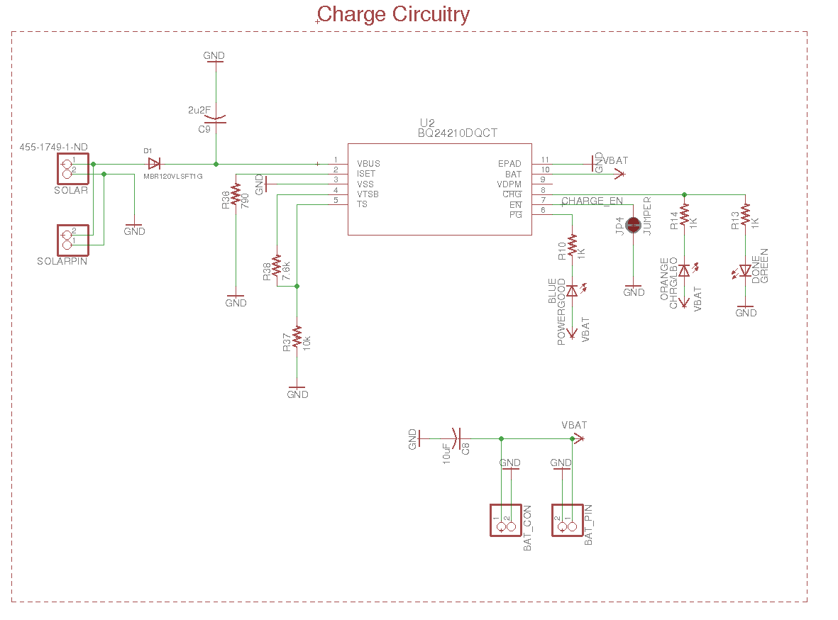
The other major change was the implementation of BQ24210DQCT Li-Po charger. The previous charger I was using was basically a copy of an Adafruit solar-LiPo charger IC but that required a monster 4000uF capacitor so that wasn't really going to work. This chip is much smaller and seems more suited to the task.
I will also be posting the updated BOM via Findchips and will post pictures when I recive the board! I am pretty sure that I failed to correct many wiring mistakes but that is just how you learn, right?
Discussions
Become a Hackaday.io Member
Create an account to leave a comment. Already have an account? Log In.