Alright! So it's been a while since the last update. College Happened.
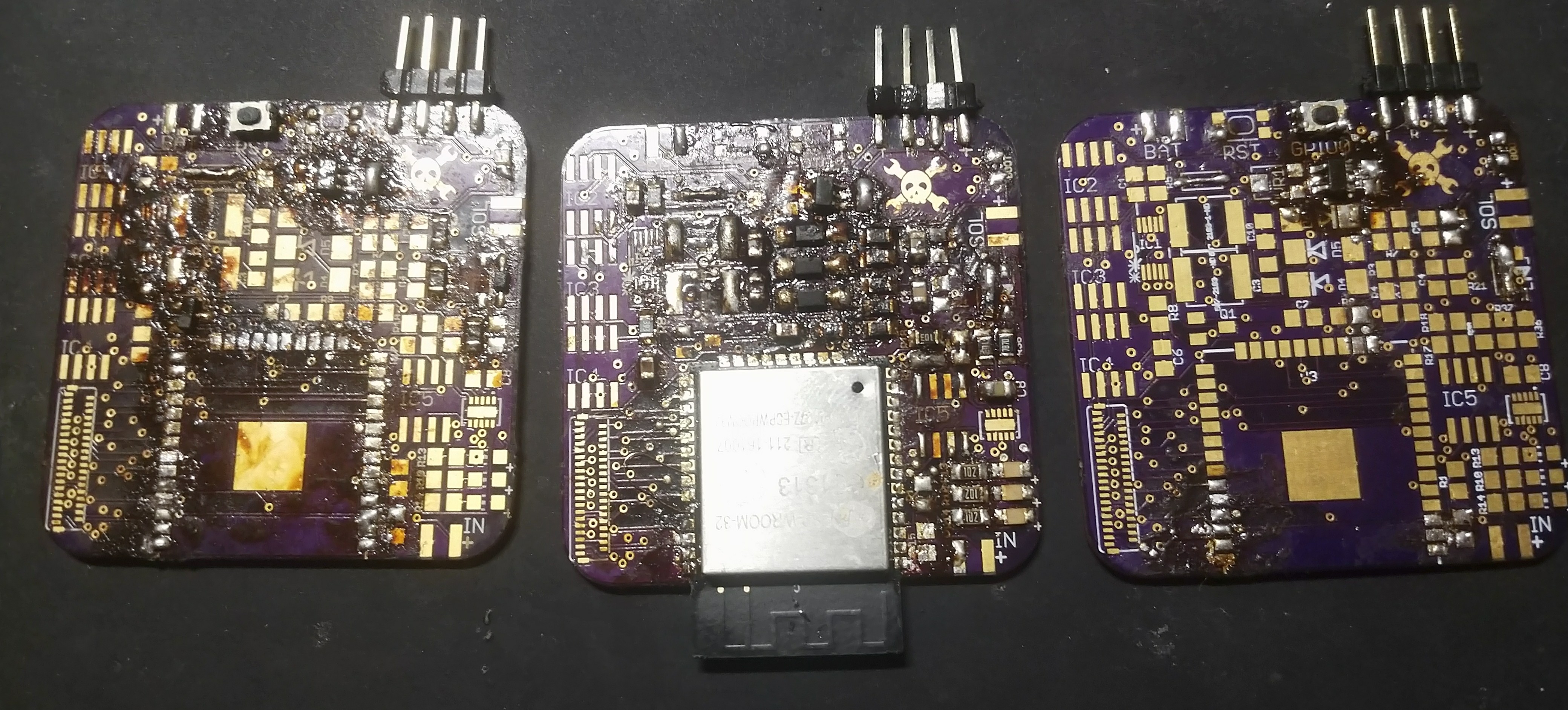
Since the last update I made a new pcb which is smaller, better, faster, stronger, etc. I used the ESP32 this time and I have to say that it was nice to get rid of those shift registers. In this version I also switched to 805 components to save on size.
I also moved the d-pad of buttons onto a separate pcb which really helped to bring down the costs as well.
All together the various design changes I made brought the costs of each pcb from 15 dollars to 5 dollars.
Honestly though it doesn't really matter because it still doesn't work :)
Enjoy some pictures and then read on to find out more.

Basically I soldered up everything, and it did not work. There was a single instance where I was able to program the ESP32 and was getting output on the serial terminal and it was excellent and all was good in the world. However, things went wrong. I accidentally switched the polarity of the power leads (rookie mistake, my bad). Some magic smoke was let out of the regulator but when I tested it on the ol' multimeter things seemed like it was in order: still a solid 3.3 volts.
Yet I was getting no output from the serial terminal and could not flash anything. So silly me I bought another ESP32 thinking that I had toasted the brain. When I replaced the ESP things still didn't work and suddenly my regulator was spitting out 4.8 volts to the ESP. Much too spicy for the ESP (arguably).
So I soldered things on different boards and yadda yadda with limited improvements with my results. I have checked the continuity on all the important traces and everything checks out. If anyone would like to help me out with this PLEASE PLEASE PLEASE send me a message. I have been working on this thing for so long (millennial time are kinda like dog years) and I still haven't gotten even the correct voltages for the e-ink screen.
If anyone would like to offer ANY help in terms of pcb design please please please send me a message and we can chat. Until then I think that I am going to try to make a mk3 pcb which will be a little more robust. See you guys next time.
 Chris
Chris
Discussions
Become a Hackaday.io Member
Create an account to leave a comment. Already have an account? Log In.