James Ots
-
Multiple Problems
05/08/2017 at 20:09 • 1 commentI had a slightly frustrating weekend on the Z80 project. Since I switched to using VHDL instead of schematics, everything stopped working.
Of course, I had finished wiring up the RAM chip as well, so I wasn't sure if that was the problem, or if I had written bad VHDL code. But I switched back to the old schematic version of the CPLD code, and it still didn't work. Everything was very strange. And the power supply seemed to be running hotter than previously.
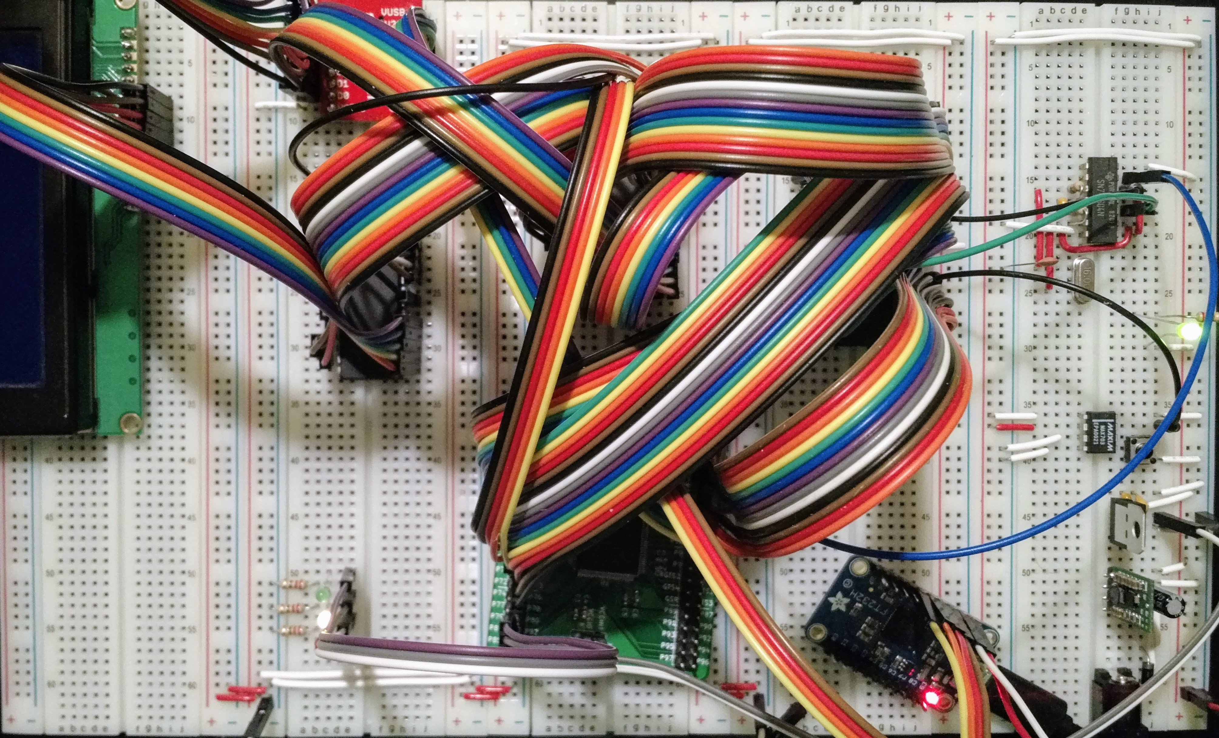
Eventually, while I was checking all the wires were plugged into the breadboard properly, I suddenly noticed that the RAM chip was plugged in in reverse. Which meant it was getting 5v on its ground connection and was grounded on it's Vcc input. And when I touched it, it was burning hot. Which probably also explained the hot electronics smell.
I'm assuming I've blown up the chip, but it shouldn't have affected anything else on the board (hopefully!), so I've replaced it with another one, and things have started looking better. I can send bytes down through the FTDI and the LEDs flash. Except that the LEDs aren't counting in binary correctly, and after a number of flashes (sometimes one or two, sometimes hundreds), the WAIT line goes high and it stops reading from the FTDI.
Then I realised that I was still powering the computer through the USB JTAG board, and now that the RAM is also connected the meagre amount of power from the USB connector might not be enough to make the system work. So I switched back to my 1A power supply and it all started working perfectly again.
-
Serial Input
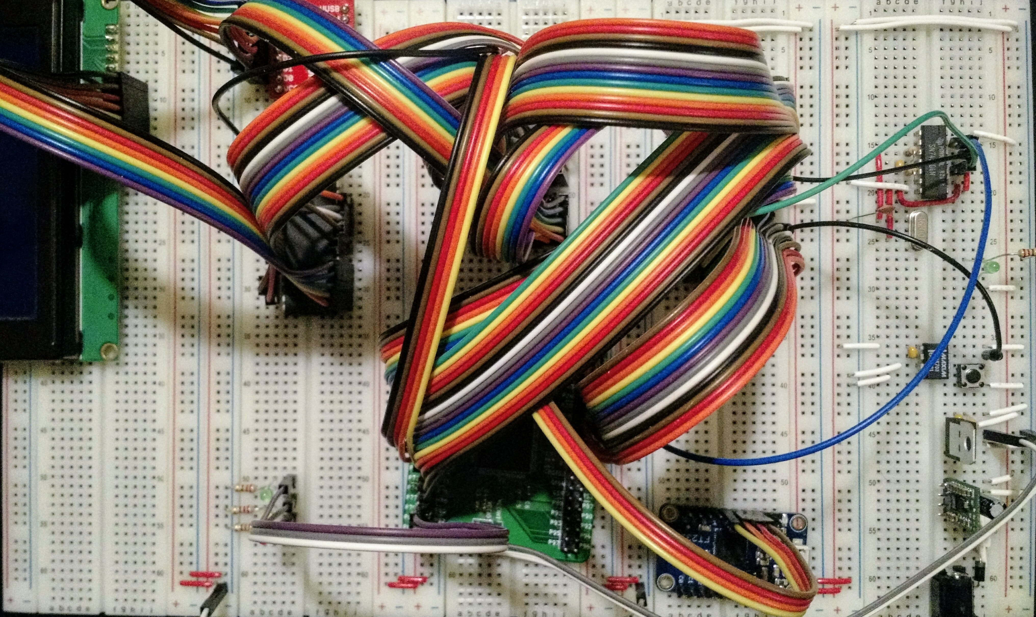
05/05/2017 at 23:15 • 0 commentsJust a small addition today. I tried to work out what the smallest testable thing I could do with the serial port was. (The serial port is on an FT245R breakout board, but I always erroneously refer to it as the FTDI). So I wired the FTDI into the CPLD, and then added a bit to the CPLD schematic so that whenever the CPU tries to read it would ask the FT245R for a byte, and if the serial buffer is empty it sets the WAIT line to low until data is available. I then wired up the green LED to the WAIT line, and connected the red and yellow LEDs to A0 and A1.
Now when the system starts up the green LED immediately goes off, as there's no data waiting. Then every time I send a byte down the serial line, the red and yellow LEDs switch on and off, counting from 0 to 3 in binary, thus proving that it is actually reading data from the serial port.
(Notes to self: I should put the Linux FTDI programme on a public git repo, and I should add screenshots of my schematics. And then switch to using VHDL instead of schematics, and also put it in the repo. And add the KiCAD schematics to the repo.)
![]()
-
Flashing lights
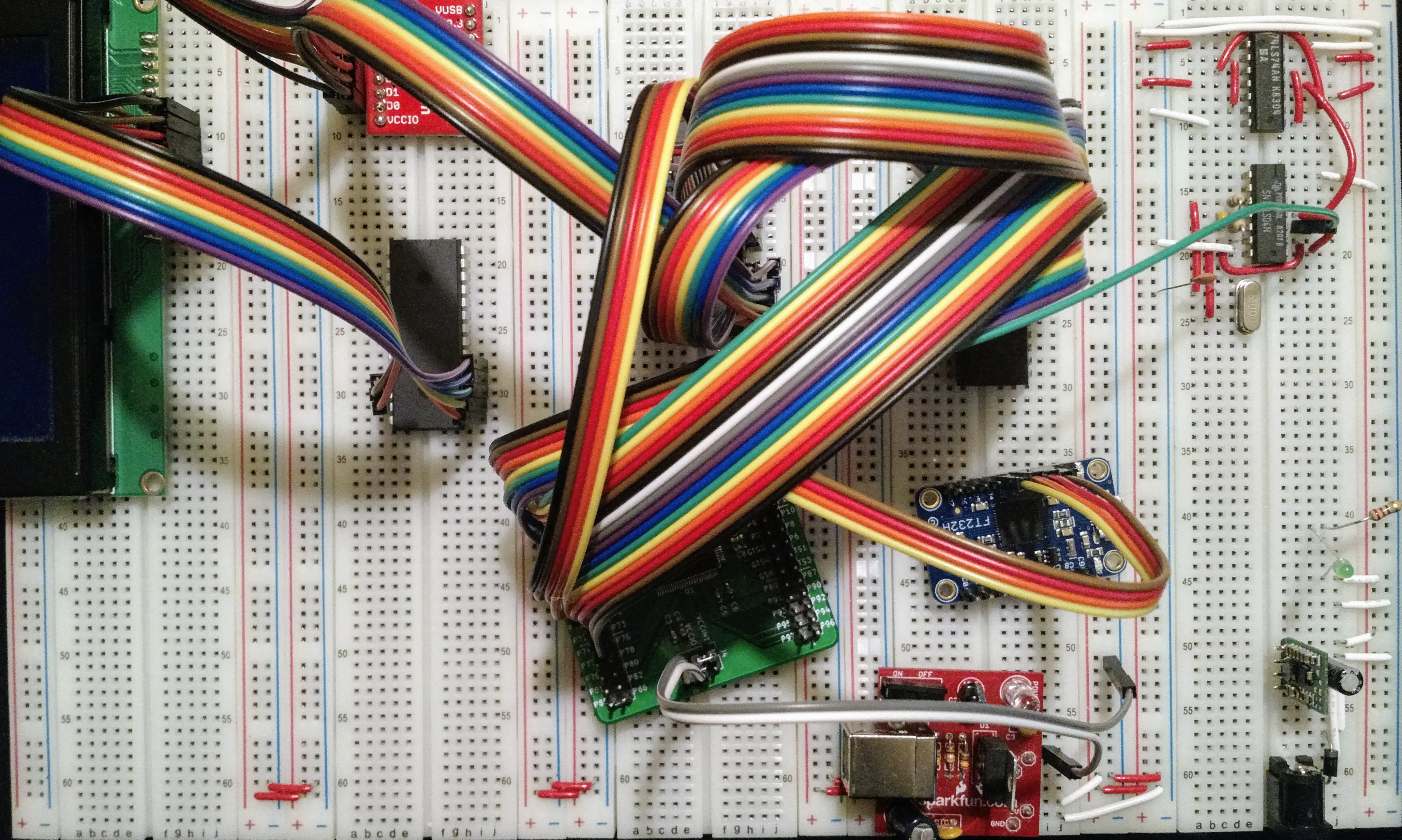
05/04/2017 at 21:15 • 0 commentsThis evening I got all the Z80's control pins connected up to the CPLD (it's a Xilinx XC95144XL, by the way), as well as three LEDs, for testing things with. I've also added a MAX703 to provide a reset signal, and replaced the previous 3.3v power supply with an LD1117AV33, which is much more compact. I decided to put the 3.3v clock signal through the 74LS04 in order to get it up to 5v, just to be sure.
The CPLD is currently programmed to hold all the control inputs high, and hold all the data lines low so that the CPU will execute NOP instructions, and the address will slowly increment. I connected the LEDs to A13, A14 and A15, which should make them flash at 15, 30 and 60Hz or thereabouts, I think. Just about slow enough to see them flash (at least at 15 and 30Hz), and my multimeter should be able to measure it. Unfortunately, nothing happened.
So I programmed the CPLD to flash the green light on and off fairly slowly. Which should work, as it was working yesterday. Alas, today it didn't work.
I was starting to run out of things to check. The reset circuit was working correctly, the clock circuit hasn't been touched, the CPLD still looks like it's working (the xc3sprog programme can still see it). Eventually I had a look at the VHDL code which ISE generates from my schematic, and noticed that it was all wrong. Aha! Yet again, I had done something stupid. Yesterday I had started a new CPLD project on my computer to put the Z80 code into, but I was still loading the old test code onto the board. D'oh! I uploaded the correct code, and the lights started flashing perfectly!
This means that the Z80 works. Hooray! And I tried putting the 3.3v clock signal into the Z80 and it wasn't happy with it, but it seems to be okay with 3.3v on the other inputs.
The next stage, I think, is to connect up the FTDI USB port properly so that I can run a programme to flash the lights differently, and then wire up the RAM and ROM.
![]()
-
A Clock
05/03/2017 at 20:36 • 0 commentsWell, I blew up the 3.3v buck converter somehow. The voltages all started dropping and the converter got incredibly hot, and now it doesn't work. Fortunately, it doesn't seem to have damaged anything else. Also fortunately, I had a USB power board with a 3.3v linear regulator on it lying around, which I am now using instead. I've ordered an LD1117 to put directly on the breadboard to save some space.
I spent far too long trying to get my clock generator working this evening. I was hampered slighly by the fact that I don't have anything which can measure a 4MHz signal, and while I had my CPLD set up to divide its clock signal by 2^20, I forgot that I'd also added a button input just to try things out, and so the signal wouldn't be divided unless I pressed the non-existent button. When I reloaded the CPLD with a new programme which didn't require the button, I discovered that my clock is working just fine, and probably all my other variations of clock circuits would have also been fine if I'd been able to test them properly.
I'm going to remove the flip-flop divider from the breadboard and divide the clock on the CPLD instead, because it might be useful having a 16MHz clock in there when I come to adding an SD card, so that it can read and write a little faster. Depends if I have enough macrocells left when I get there of course, and whether the CPLD can cope with having two clocks.
Another thought: TTL devices should be able to cope with the 3.3v signals from the CPLD, but will the Z80 be okay with having a 3.3v clock? We will see…
![]()