 Bruce Land
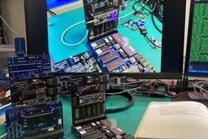
Video VGA 640x480 displayed from SDRAM, in 16-bit color.
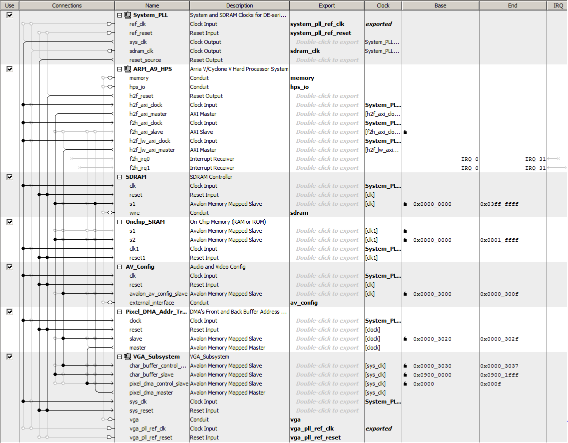
A stripped down display system uses SDRAM as a frame buffer. The top
level Verilog only connects the Qsys exports to the i/o pins and has no
other logic. The Qsys layout is modified to support 16 bit color. The
Qsys modifications:
- Inside the VGA subsystem
- The vga_pixel_dma module:
- has the address modifed to 0x00000000, the base of SDRAM.
- address mode changed to consecutive.
- color space 16-bit.
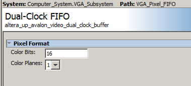
- The dual-clock fifo module has color bits changed to 16-bits.
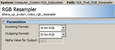
- The RGB resampler is changed to 16-bit input.
- The vga_pixel_dma module:
- Output from the VGA DMA controller in the top-level Qsys is disconnected from on-chip-sram
and connected only to SDRAM. - The AXI-bus, HPS master remains connected to SDRAM so that the HPS can read/write VGA screen.
The HPS pixel writing macro is modifed to allow 16-bit writes to the bus, and uses the consecutive format:
// pixel macro
#define VGA_PIXEL(x,y,color) do{\
int *pixel_ptr ;\
pixel_ptr = (int*)((char *)vga_pixel_ptr + (((y)*640+(x))<<1)) ; \
*(short *)pixel_ptr = (color);\
} while(0)
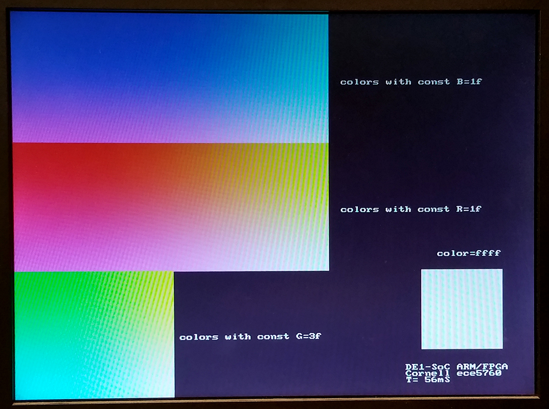
Color coding is 16-Bit RGB. This format uses 5 bits for red, and 6 bits for green and 5 bits for blue.
If R and B are 5-bit integers and G is a 6-bit integer then color = B+(G<<5)+(R<<11);
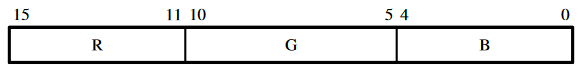
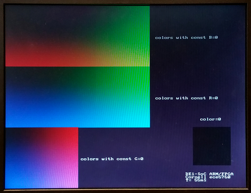
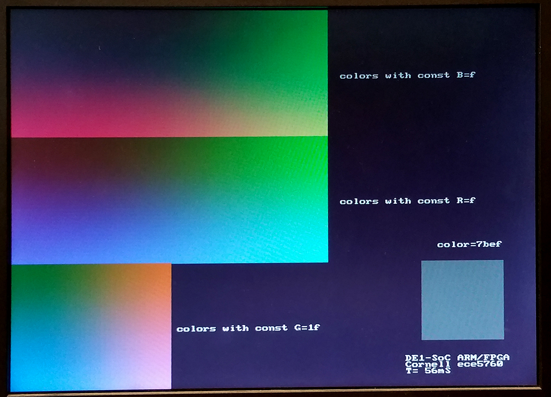
A color-picker program allows you to specify R, G, B values,
displays the color in the lower right, and shows 2D slices through the
3D RGB space, axis aligned, which include the specifed (R,G,B) point.
The top slice is the red-green plane, the middle is blue-green, and
bottom is blue-red plane. Three examples are shown below through points
black (0,0,0) , medium gray (15,31,15), and white (31,63,31).The HPS
perfrormance program linked below prompts for color mask values to set
ranges for RGB, then draws 1000 discs with random colors constrained by
the RGB masks.
 Xark
Xark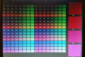
 JLAM
JLAM
 Tyler Klein
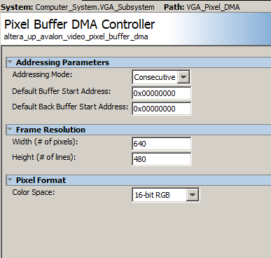