 Tron9000
This evening I assembled the test harness to confirm that my proposed harness design works.
First a quick sketch:
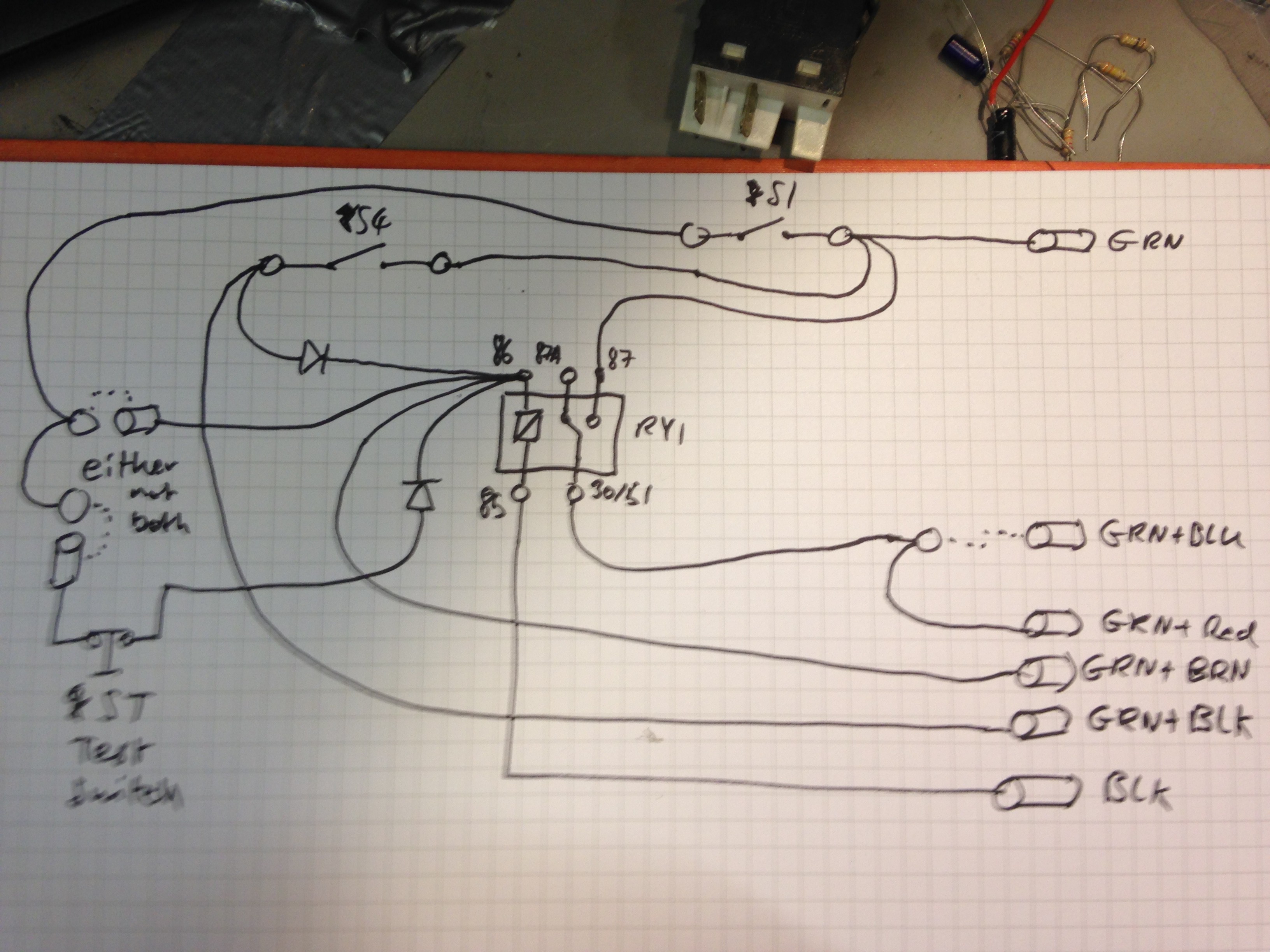
This is not representative of the final harness, ongoing improvements during construction. For example the 2 diodes: I decided to use a twin diode in a TO-220 package I salvaged from a PC SMPSU. The Test switch will basically a manual input from myself that will mimic the 555 timer interval box, and when the circuit is constructed, the switch can be removed and replaced with the circuit, as I designed it with crimp faston fittings.
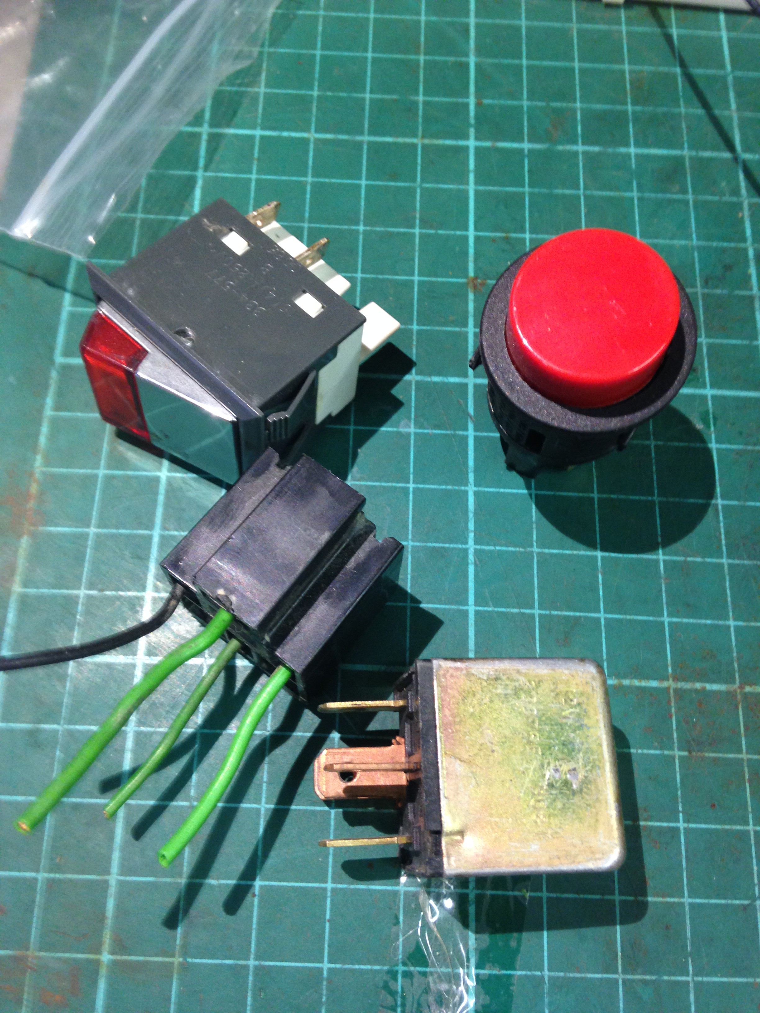
I then sourced some more switches and an automotive relay:
and sourced some wire:
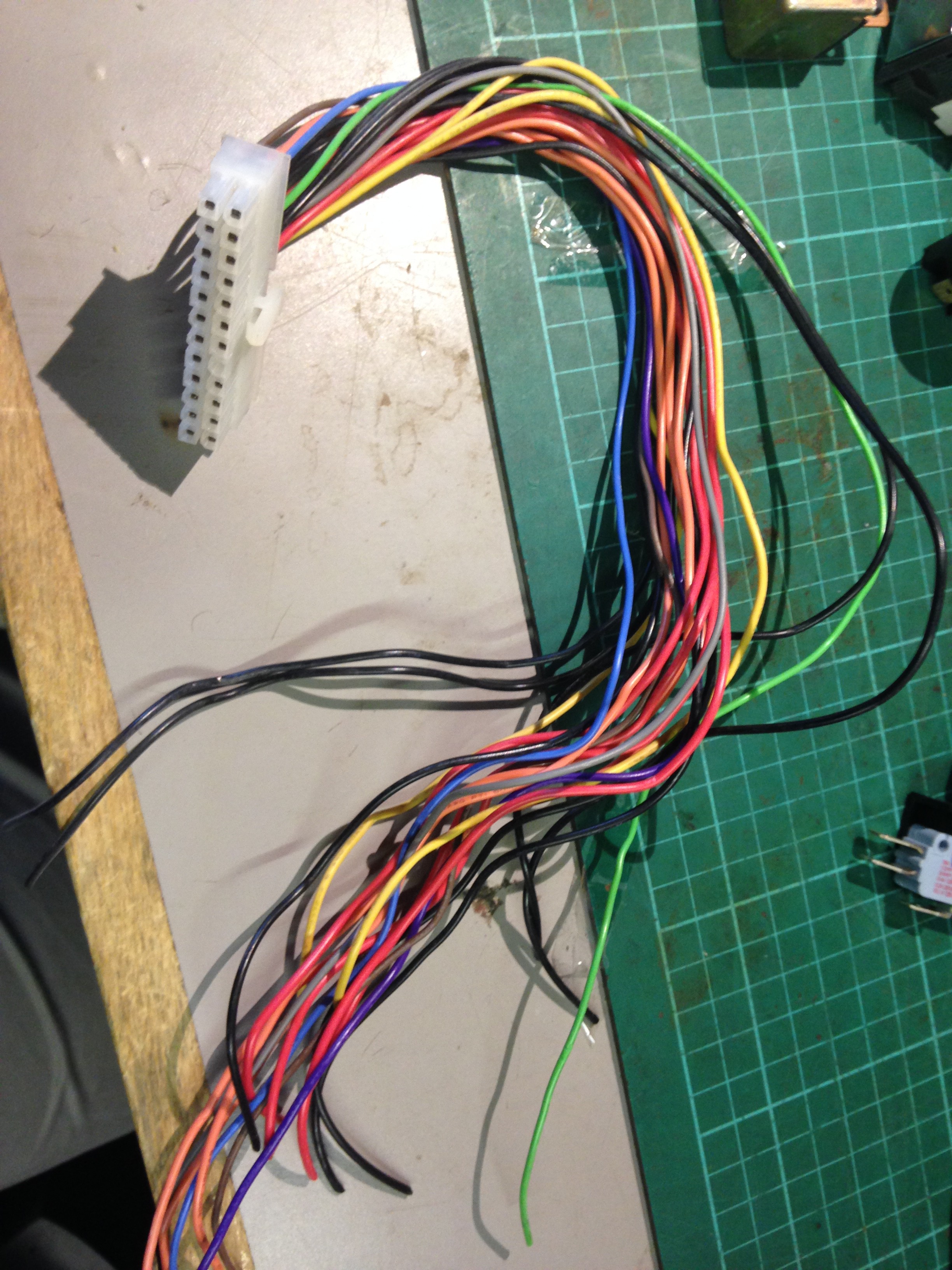
Pro-tip: ATX power supplies are a good source of decent gauge wire. So after about an hour of stripping wire and crimping connectors the harness was complete:
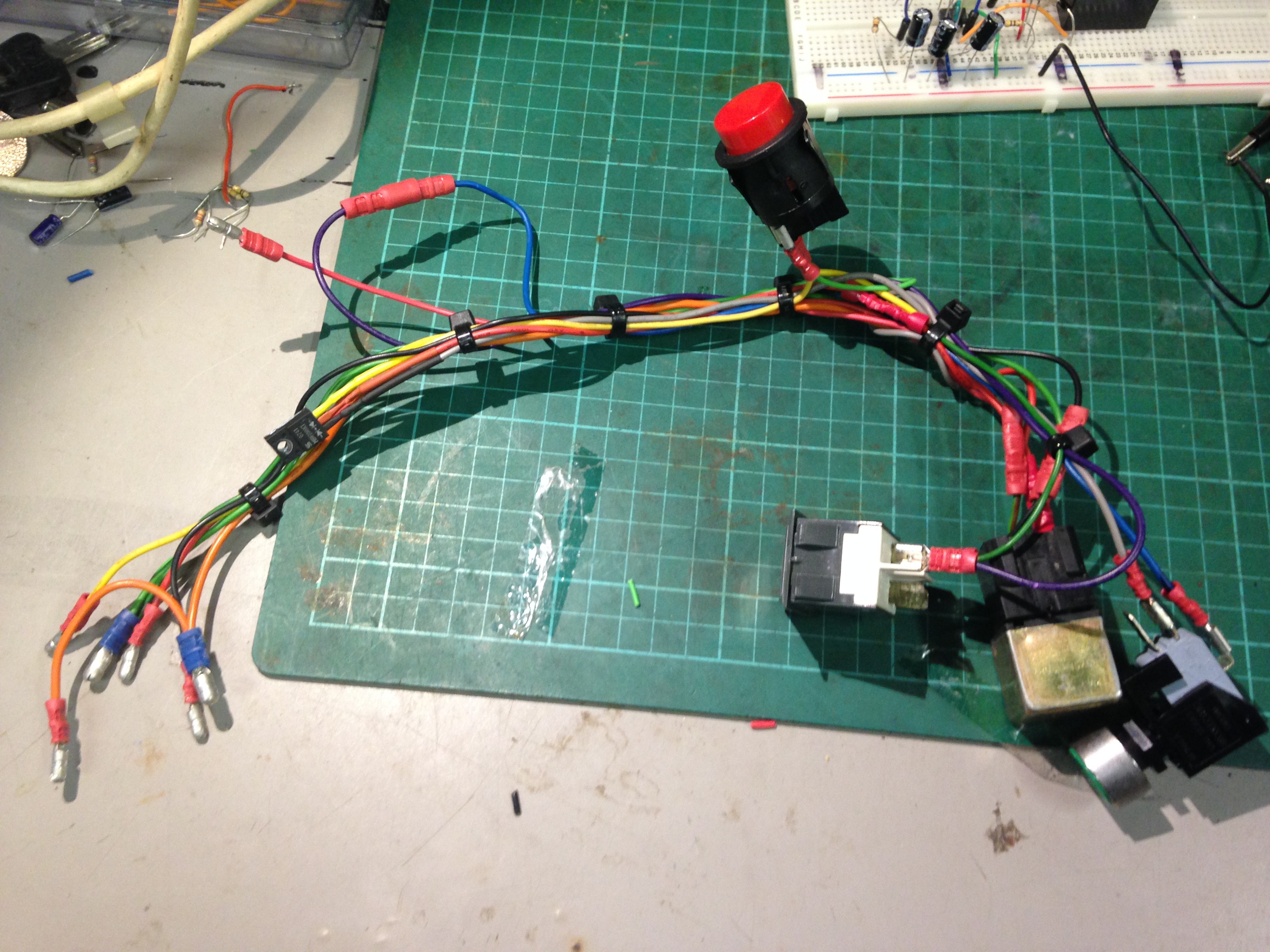
I'll be testing it by pluging it into the wiper socket on the landrover harness later.
Discussions
Become a Hackaday.io Member
Create an account to leave a comment. Already have an account? Log In.