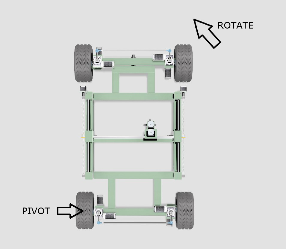
If the WEEDINATOR is navigating a turn and has it's inside wheel at 45 degrees, the outside wheel is NOT 45 degrees, it's more like 30 degrees. Also, the inside wheel may be turning at 1 km/hour, but the outside wheel will be significantly faster, more like 1.35 km/hour.

When working out the geometry, a few assumptions are made:
- The chassis will pivot about one of the back wheels as shown in the diagram above.
- The effective centre of the pivot circle will move along a line extended from the centres of the two back wheels, depending on the angle of turn.
- The geometry will take the form of a sine curve.

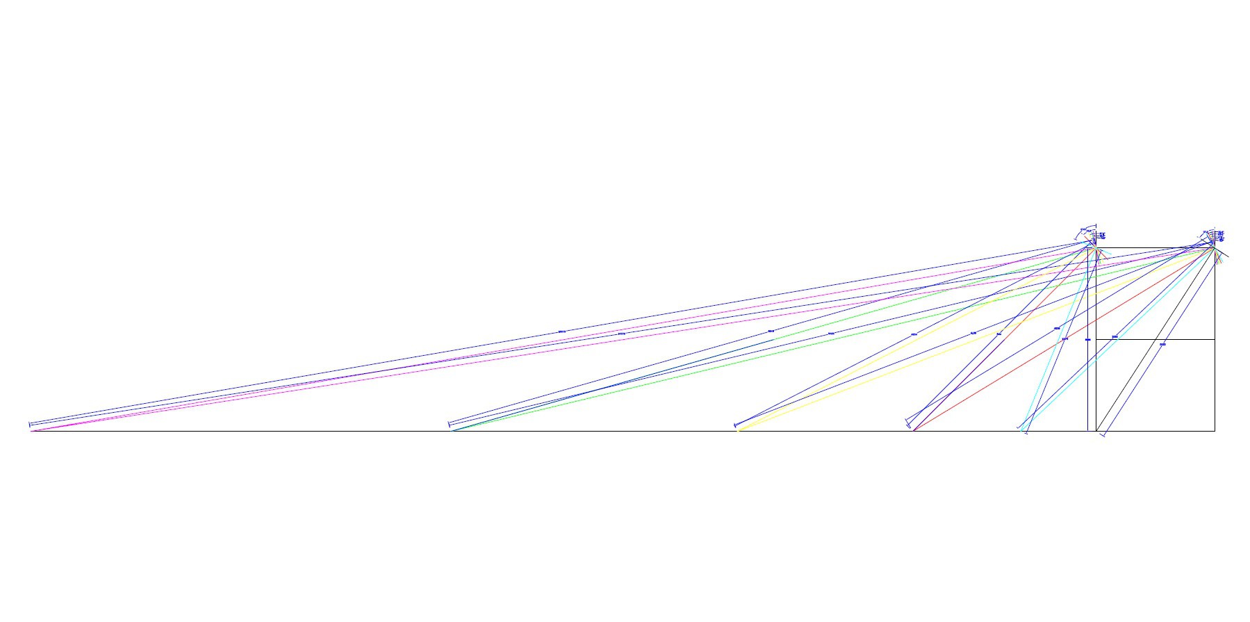
A full scale drawing was made of the WEEDINATOR front wheels and chassis with 8 different permutations of inside wheel angle between 0 and 90 degrees and the respective turn centres were mapped out as shown in the drawings above.
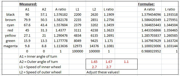
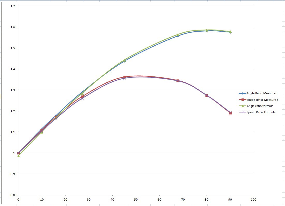
The effective radii were measured from the drawing and plotted on a graph in Microsoft Excel.
Two graphs were produced, one of the ratio of the left and right front wheel axles and another for the ratio of the two radii for each particular turn angle.
I then 'fudged' up some formulae to mimic the empirical results based on a sine curve. One of the fudgings looks like this:
speedRatio= (sin(inner*1.65*pi/180)+2.7)/2.7; // inner is the inner turn angle.
The curves were fudged by changing the values shown in red in the excel file until the curves fitted together.


Full details and downloadable files are shown here:
https://www.instructables.com/id/WEEDINATOR-Part-4-Differential-Steering-Geometry-C/
 GOAT INDUSTRIES
Discussions
Become a Hackaday.io Member
Create an account to leave a comment. Already have an account? Log In.