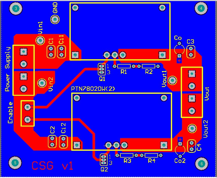
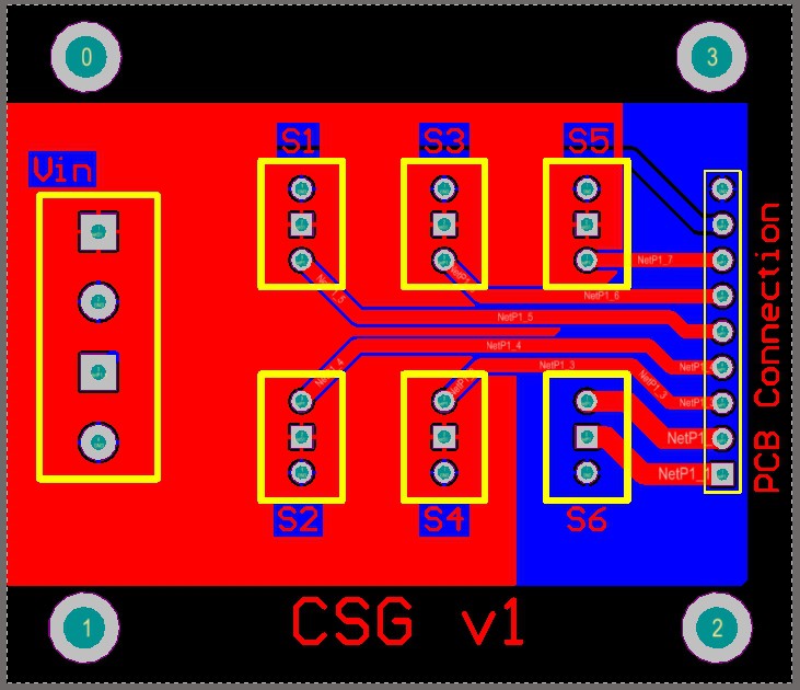
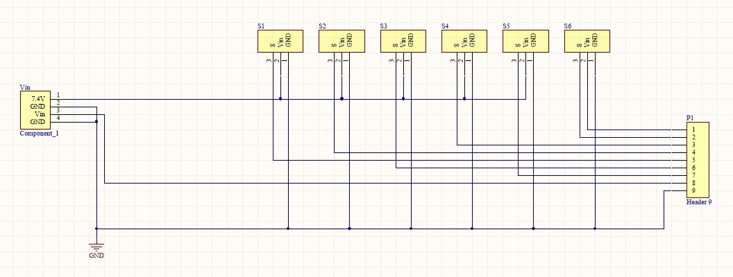
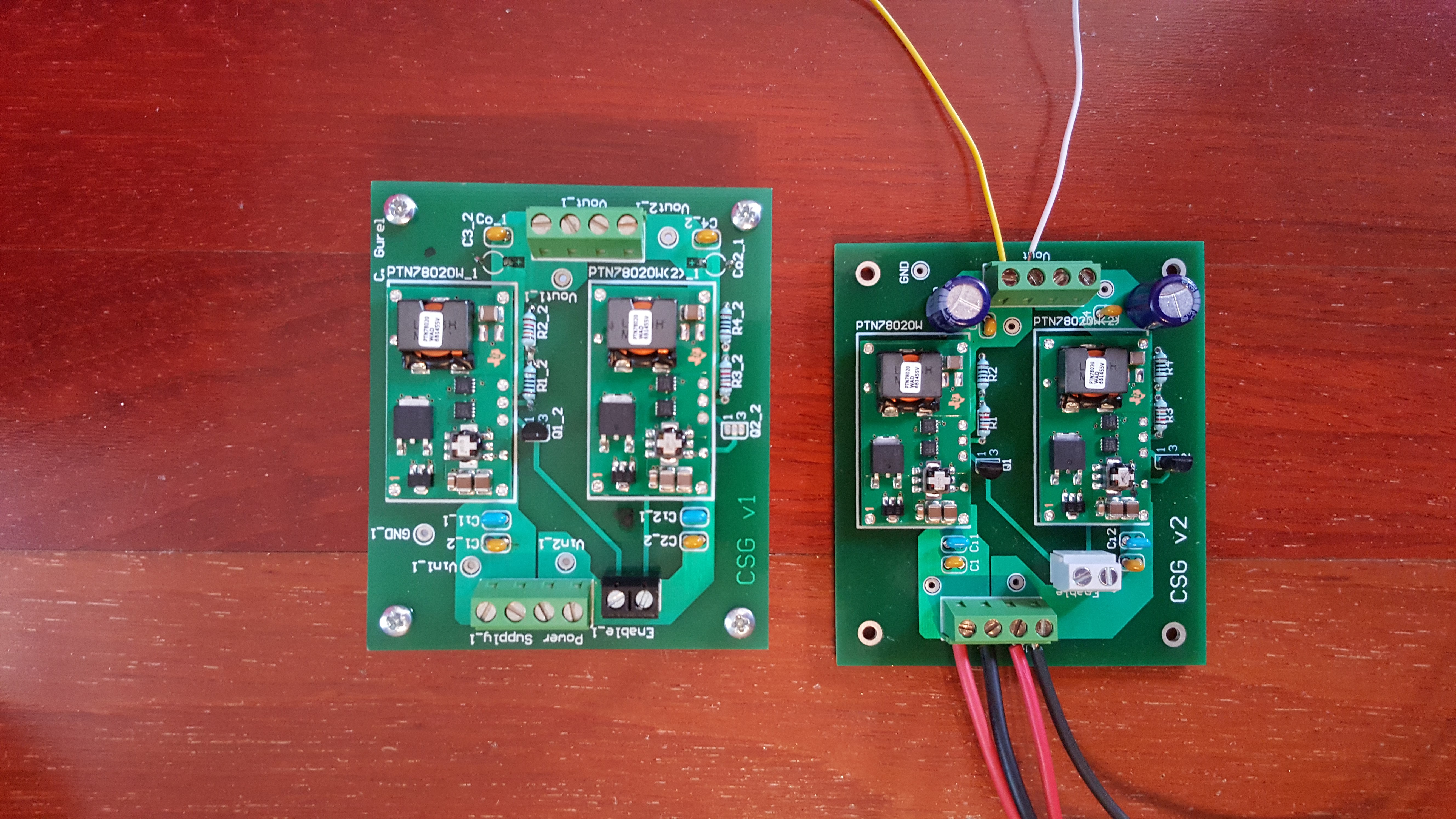
Servo motors - as you can see from the datasheet provided in the Files - require 7.4V to operate at maximum torque of 16kgcm. However our experiments showed that motor windings got damaged due to high heat that had been generated. For this reason, I decided to supply 6V to each motor. The PCB on the left, consists of 2 step down converters. It supplies variable voltage that can be adjusted anywhere between 20V to 3V and maximum 6A. The PCB on the right is the connection to the motors. 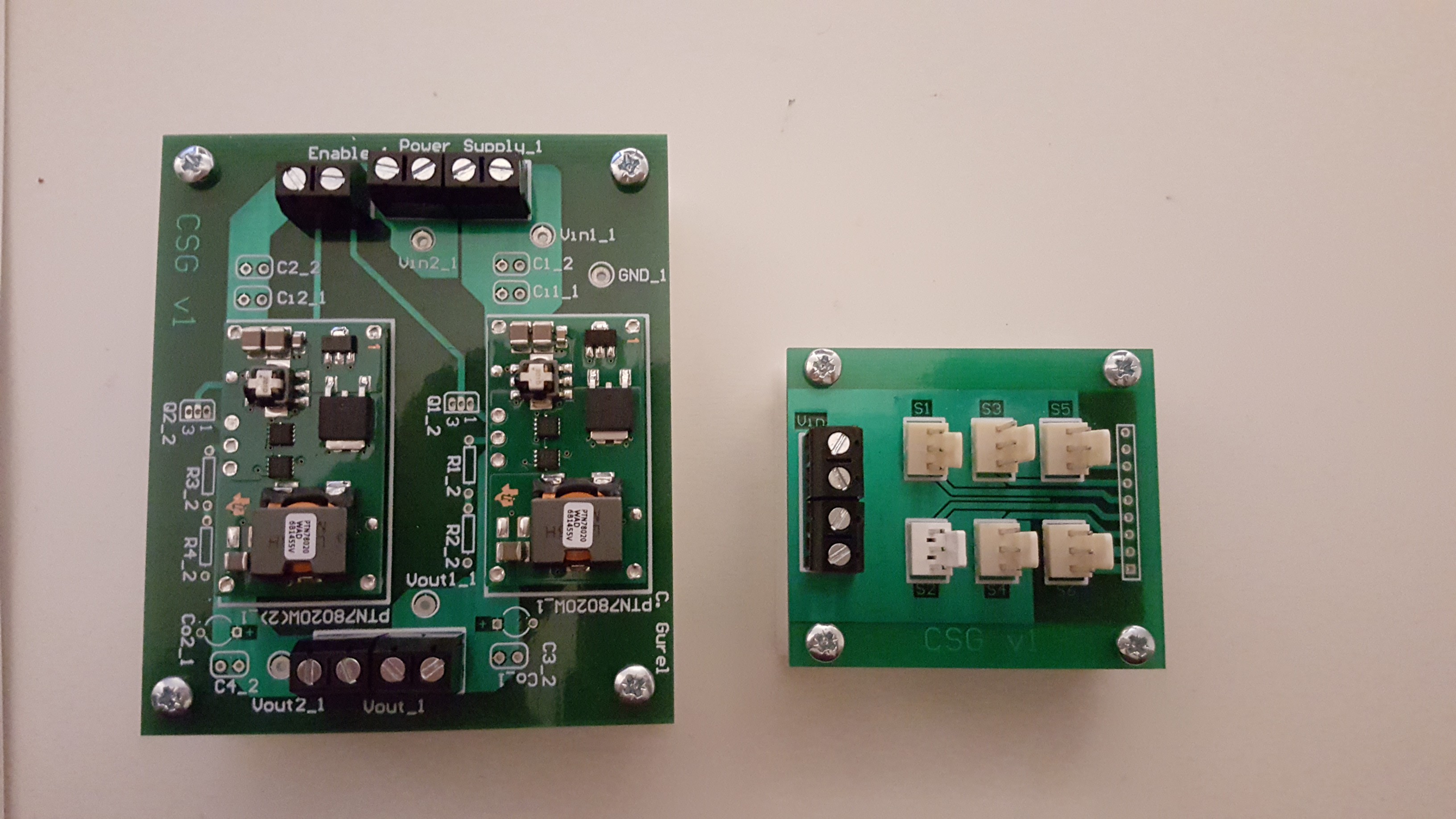
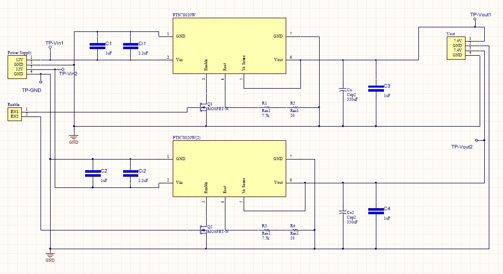
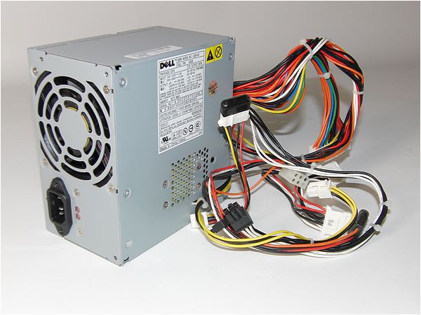
The circuits given above are supplied by a computer power supply which supplies 12V to each of the 4 step down converters. The datasheet of the converters are provided in the "files" section. The image below shows the computer power supply.
The following YouTube video is a tutorial that shows how it should be activated and connected to the rest of the circuitry.
Discussions
Become a Hackaday.io Member
Create an account to leave a comment. Already have an account? Log In.