 Chris.deerleg
The images above show the movement of the electron beam. It is necessary to apply two magnetic fields. One magnetic field is much faster as the other. The fast one causes the red line and the slower one causes a rotation of the line.
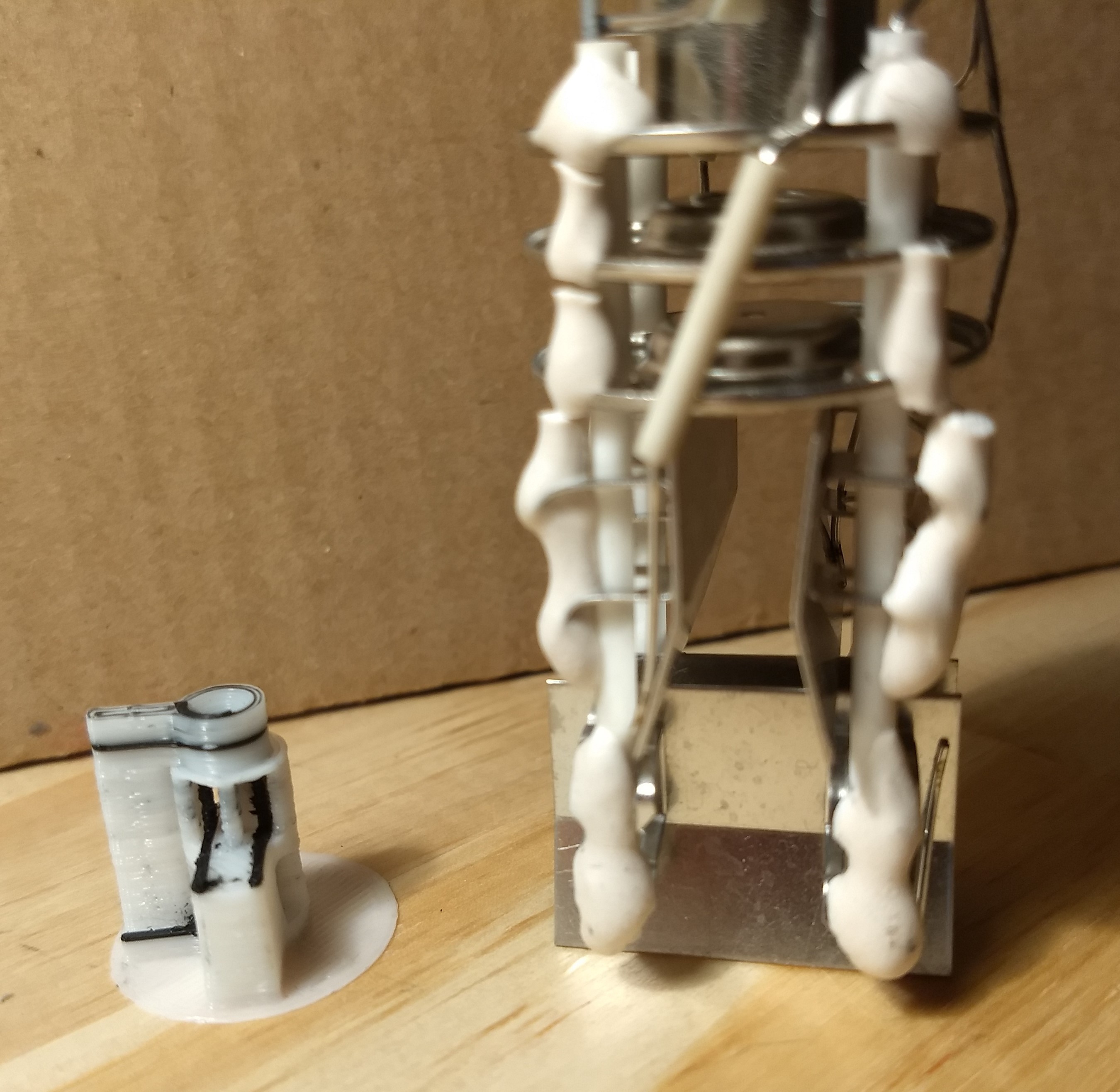
The image above shows the deflection system of a scope's CRT . On the right side is a original one and on the left side is the version out of the 3D printer. The black plastic is conductive and the white plastic build a isolation. The approach from a scope doesn't worked for me, because of the high acceleration voltage. The voltage at the deflector plates should be in the same rage as the acceleration voltage.
In the my CRT tube is the accelerations voltage about 3000V and the plasma ignition starts at approx. 400V. Therefor a plasma appear if the accelerations voltage is applied to the deflector plates. This plasma is a electron source and make it impossible to have a sharp electron beam. The right approach for the deflection is similar as the deflection in a TV tube. Two magnetic fields applied for different directions make it possible to deflect the beam.
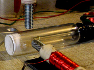
The image above shows the set up from Nyle Steiner who demonstrated on his homage how he made it.
Discussions
Become a Hackaday.io Member
Create an account to leave a comment. Already have an account? Log In.