 Chris.deerleg
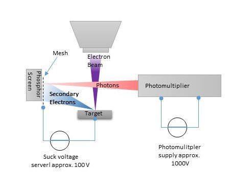
The image above show the new design which shall me enable to get a image out of my DIY SEM. The idea is that a voltage is applied between the target and a mesh in front of a phosphor screen. The secondary electrons are accelerated in the direction of the mesh. Some electrons hit the mesh and some other will hit the phosphor screen. Actually it is a screen made of a zinc sulfide. When the electron hit the screen photons are created. This photons will fly to the photomultiplier which convert the photons to electrons and multiplies these by 1.000.000.
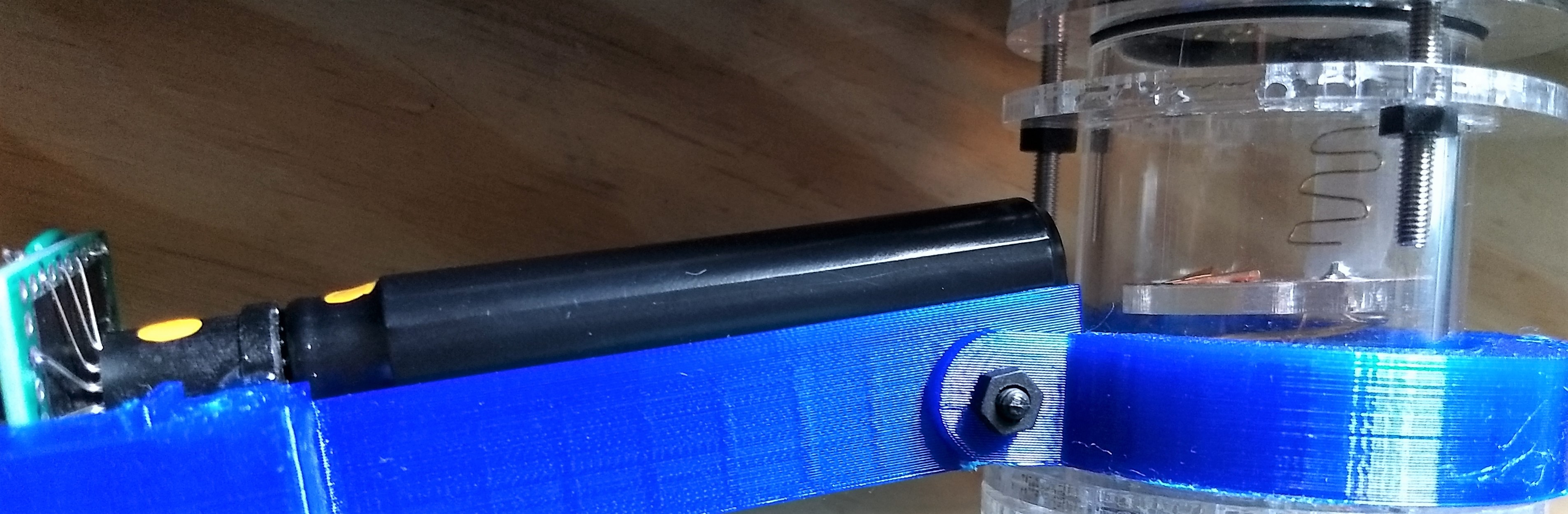
The image above show how it looks in the reality. The black long tube on the left is the photomultiplier. The withe piece behind the wire is the phosphor screen.
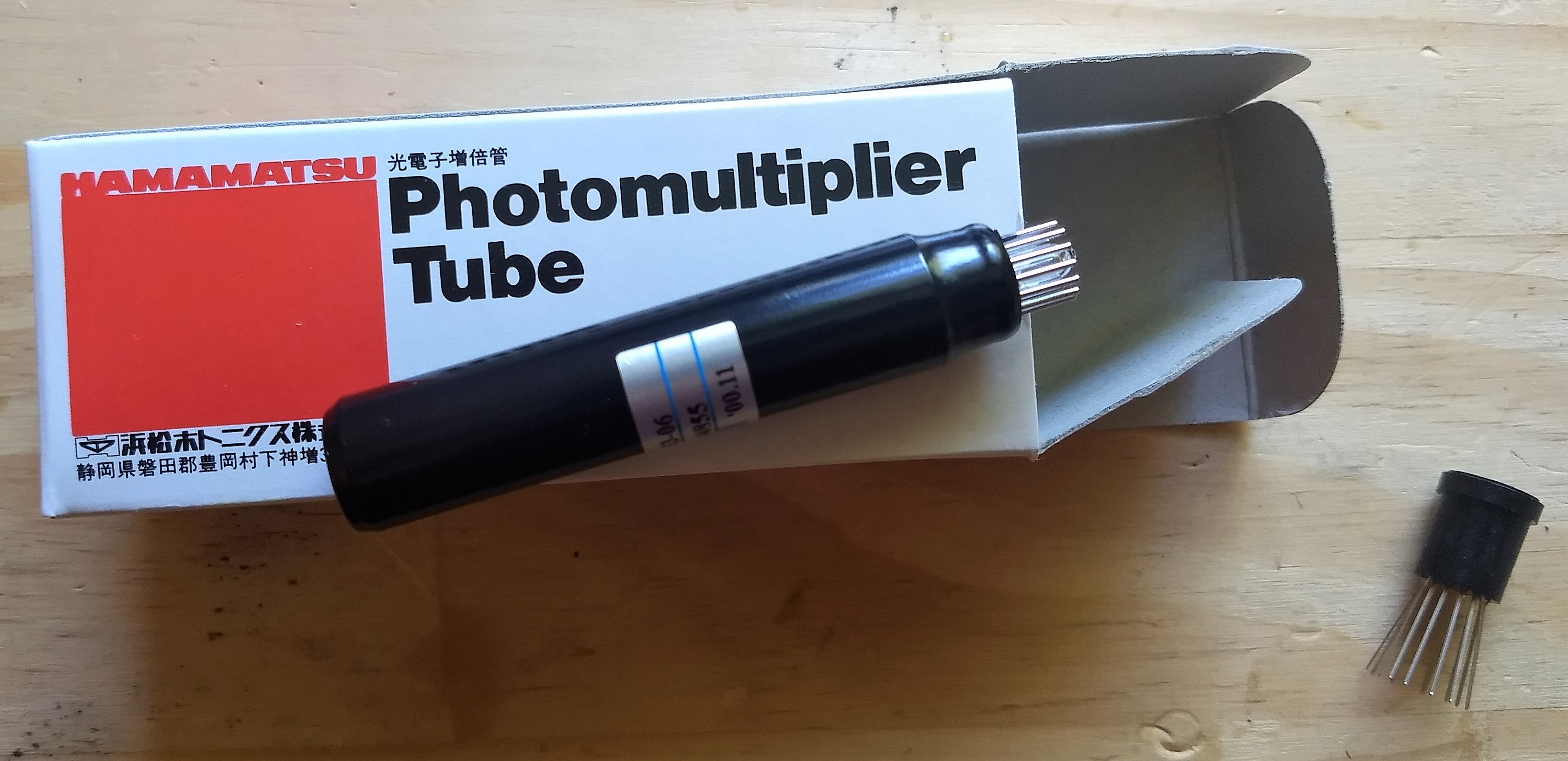
I found my photomultiplier above (HAMAMATSU R1463-06) on ebay.
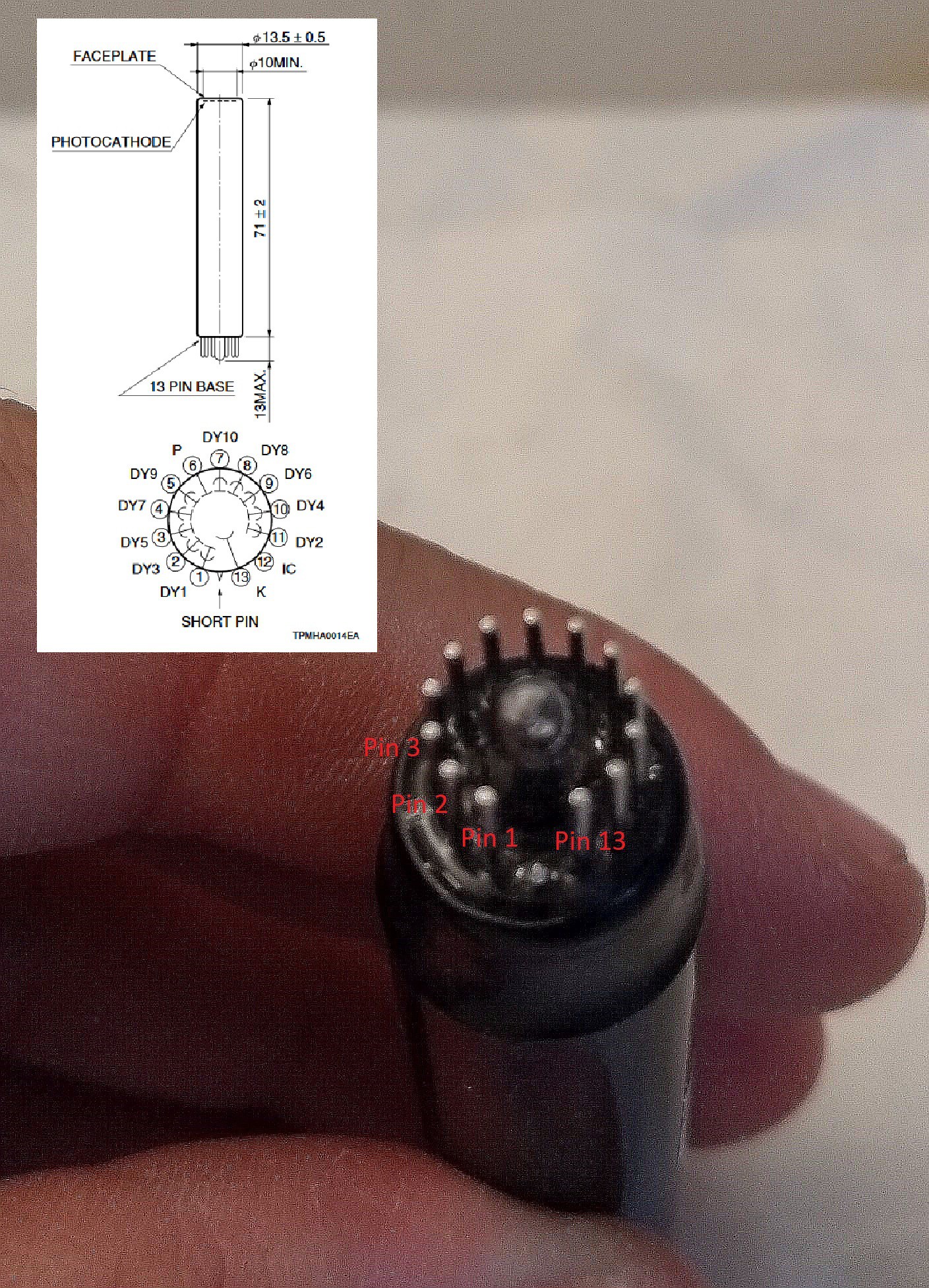
The image above shows the photo multiplier pinning.
Further I found I nice video from 1959 what explains how a photomultiplier works.
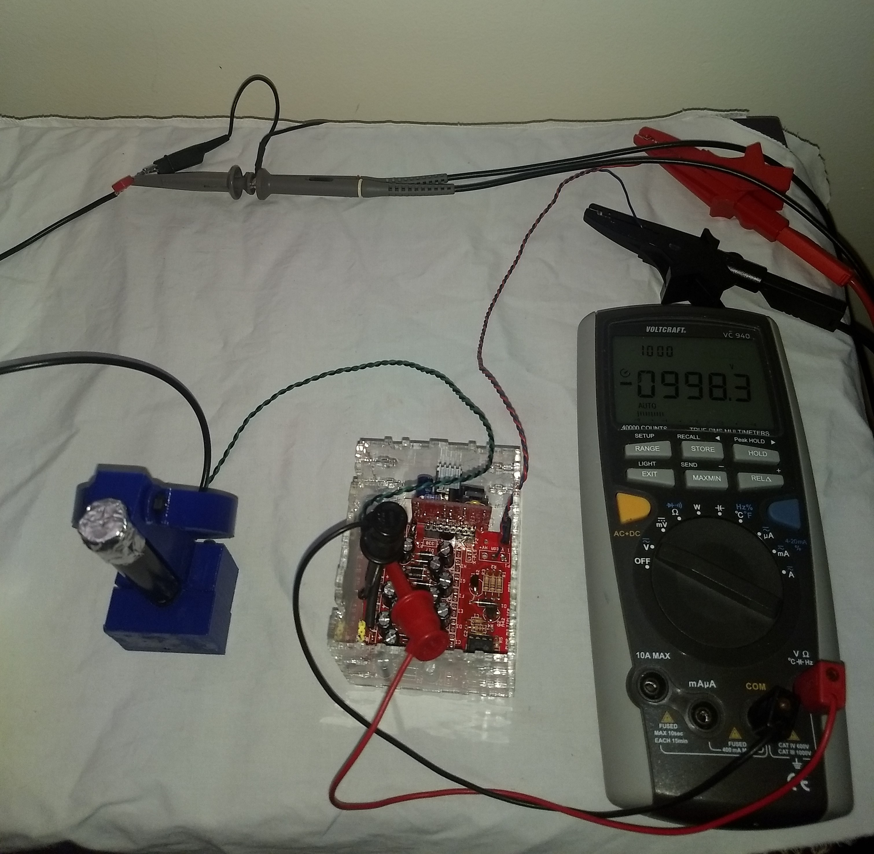
The image show the supply voltage of the photomultiplier .The red PCB is a set-up convert which convert 12V in up to 1450V.
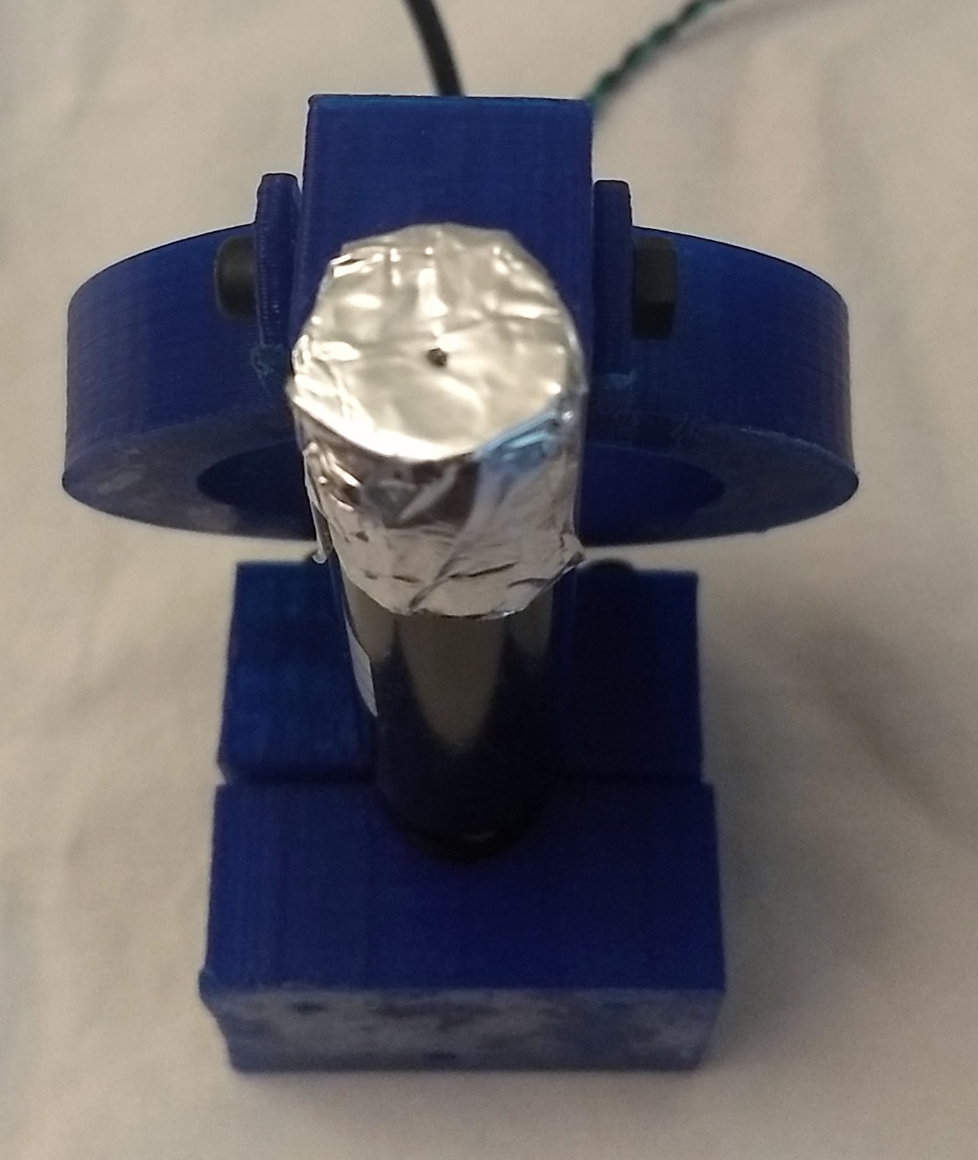
Above on the image is shown the photomultipler with aperture. The piece of aluminum foil has a small hole in it. This is necessary to prevent that the photomultiplier saturate.
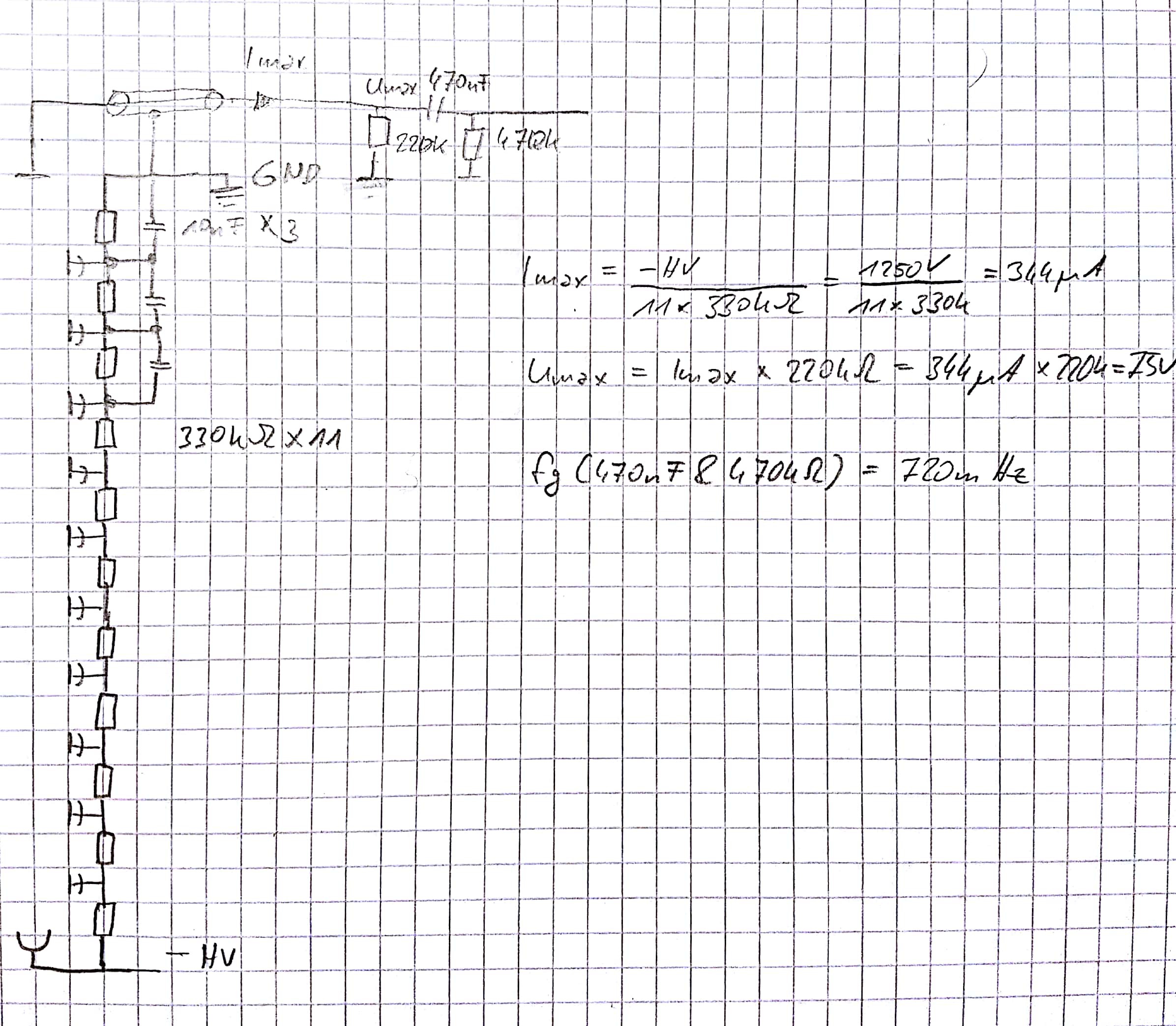
The schematic above shows the components which are required to operate a photomultiper. The negative high voltage (-HV) is divided by 11 x 330kOhm resistors. The current through the divider is 344µA @ 1250V. According to a handbook of Hamamatsu (https://www.hamamatsu.com/resources/pdf/etd/PMT_handbook_v3aE.pdf) shall be the signal current below 1/20th of the divider current. At the out is a 220kOhm resistor to limit the maximum output voltage to 75V@344µA. At the end is a high pass filter with 470nF and a 470kOhm with a cut of frequency of 0.72Hz.
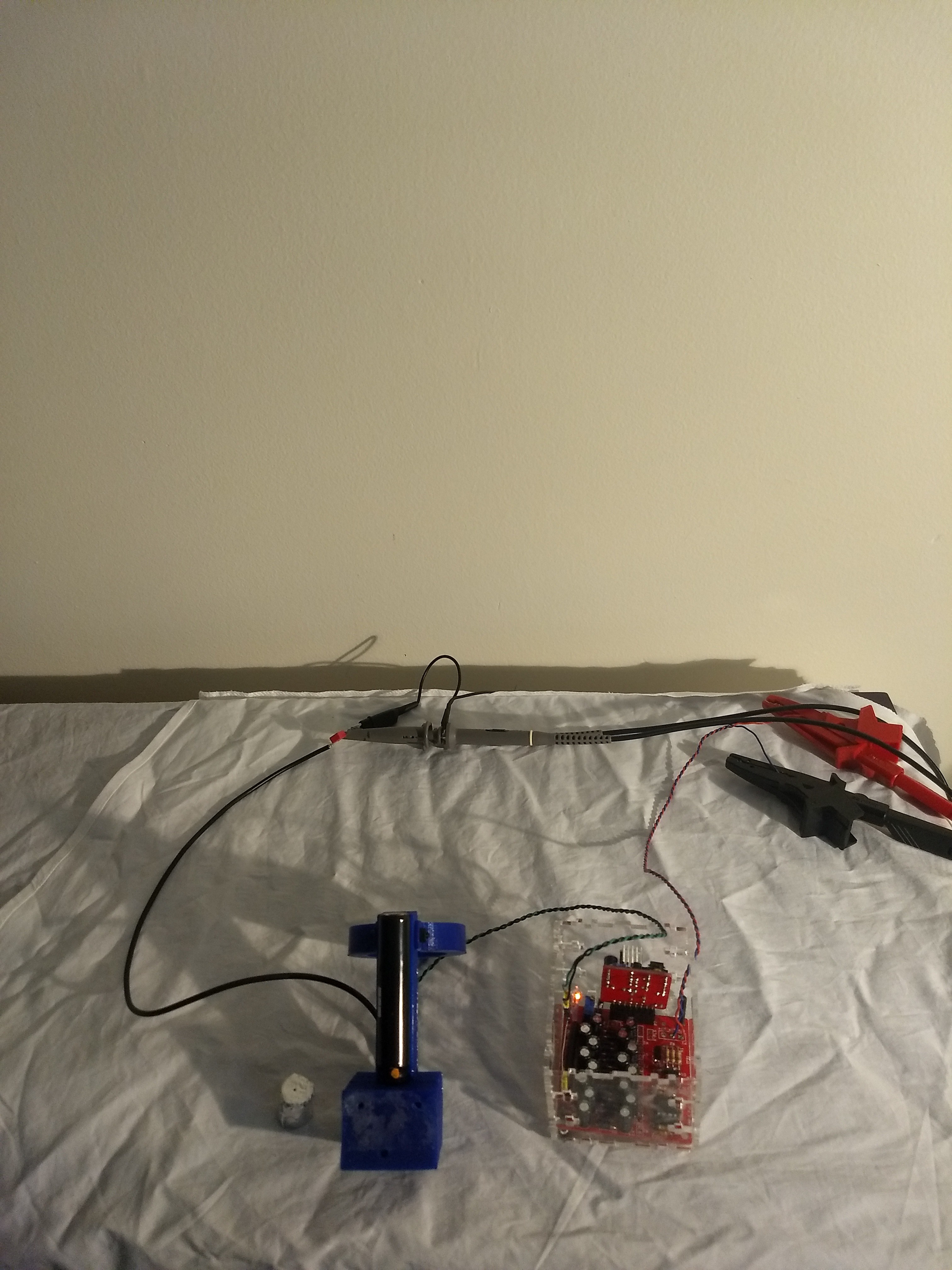 One of my first test was just to point the photomultipler to the wall and illuminate it with my desk lamp. In this test I figured out that i need an aperture.
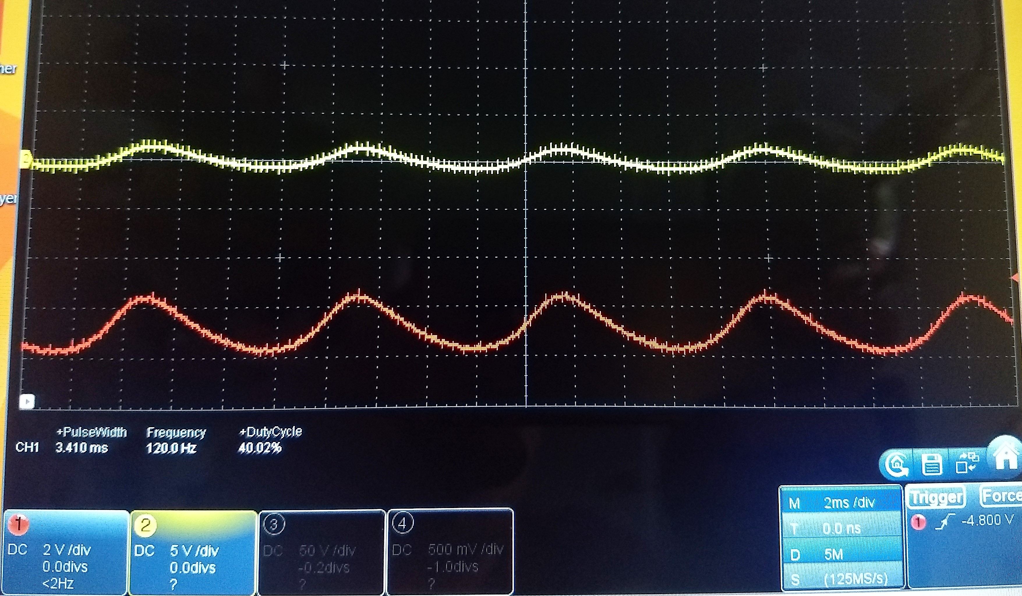
The yellow signal is behind the high pass and the red one is before. In the signal can be seen that my desk lamp has small flickering.
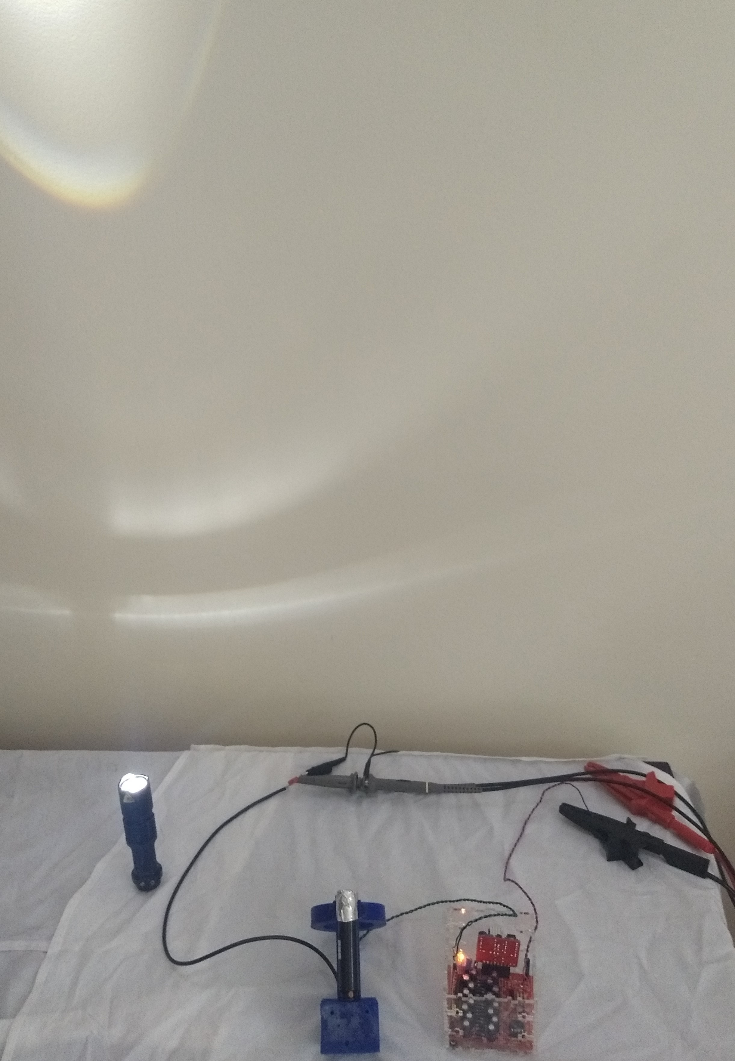
In the image above is my second test setup shown with a LED flashlight. The flash light was in a dim mode.
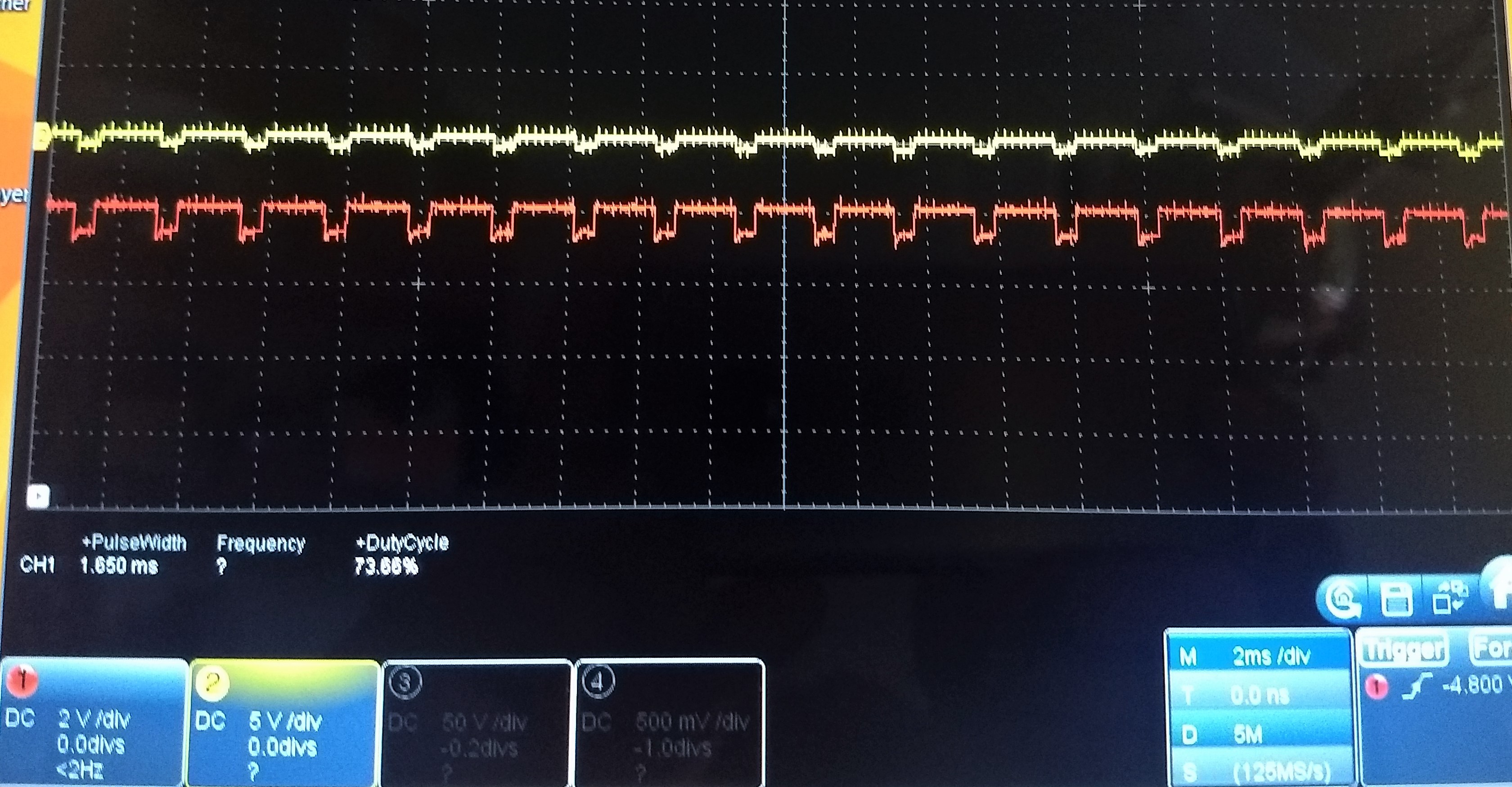
The signal above shows in yellow the signal after the high pass and in red before. The signal show good that the LED flash light use a PWM signal to dim the light.
Discussions
Become a Hackaday.io Member
Create an account to leave a comment. Already have an account? Log In.