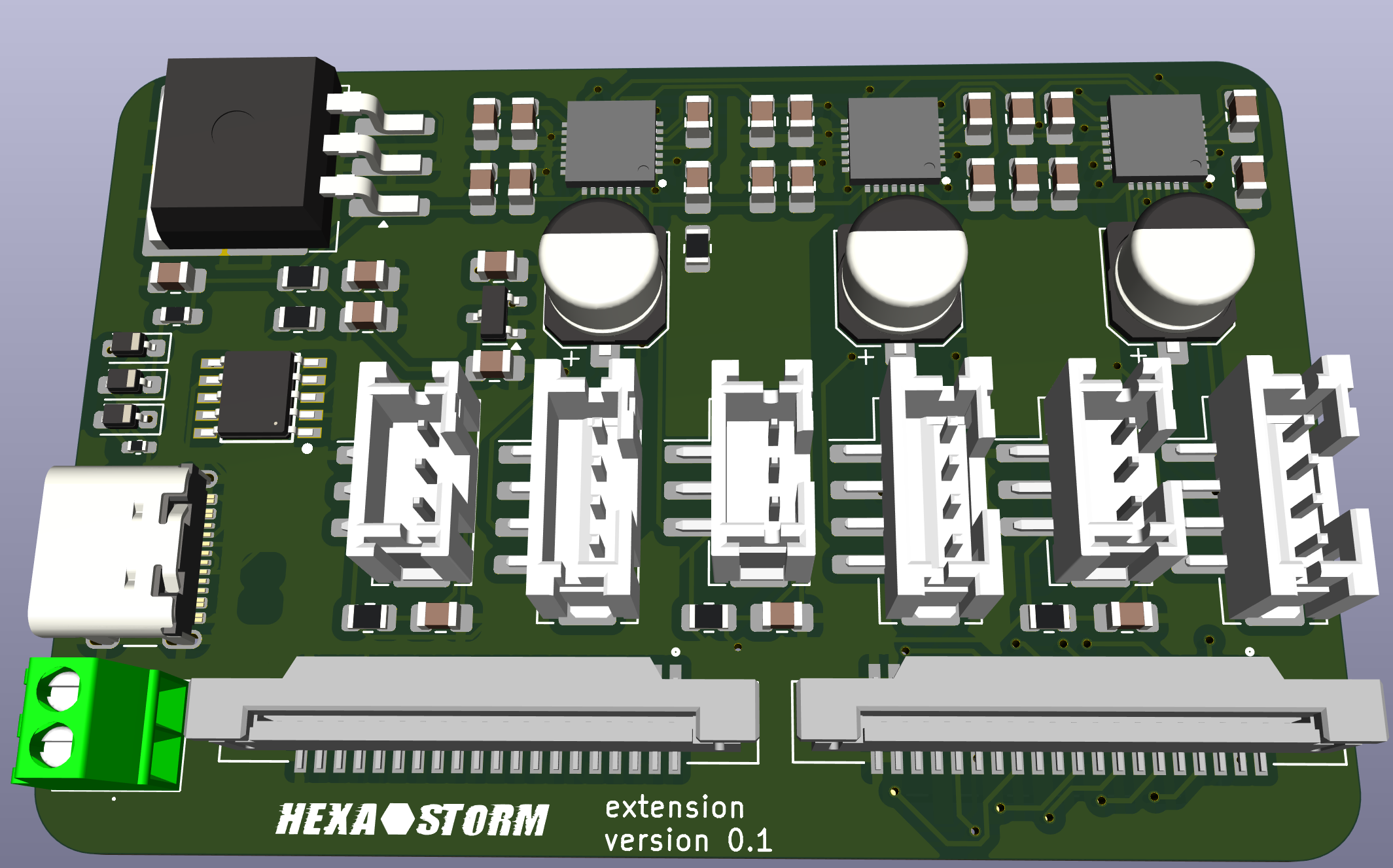
The extension module is mounted on top of a compute module. The female 20 pin header is not shown. Power is supplied via a USB-C connection requiring a 12V charger. An on-board converter (large black chip) reduces this to 5V for the compute board.
The board has three stepper drivers TMC2208 and three end stops. A 20-pin connector interfaces with the laser head. Another 20 pin connector is free to use. The laserhead needs to move less than a FFF printer due to the polygon, as such not a lot of current for the stepper motors is required. It is assumed this is less than 1 Amp.
Note: A USB-C connection with an FPGA for the laser head was initially considered but is currently postponed.

 Hexastorm
Discussions
Become a Hackaday.io Member
Create an account to leave a comment. Already have an account? Log In.
Hey gravis, cool your still looking up this project. Currently laser head is mounted on a Cartesian frame which has 3 axes and thus stepper motors and drivers. The prism motor driver is in the laser head. You need two drivers to move in a snake line pattern.
Are you sure? yes | no
You could have saved yourself a stepper driver if only you had gone with a Polar frame. ;)
Are you sure? yes | no
Sorry, I missed this update! I'm a bit confused though. Why are there three stepper motor drivers? I was under the impression that only one was needed and it's for spinning the polygon. Is the idea to drive three polygons?
Are you sure? yes | no