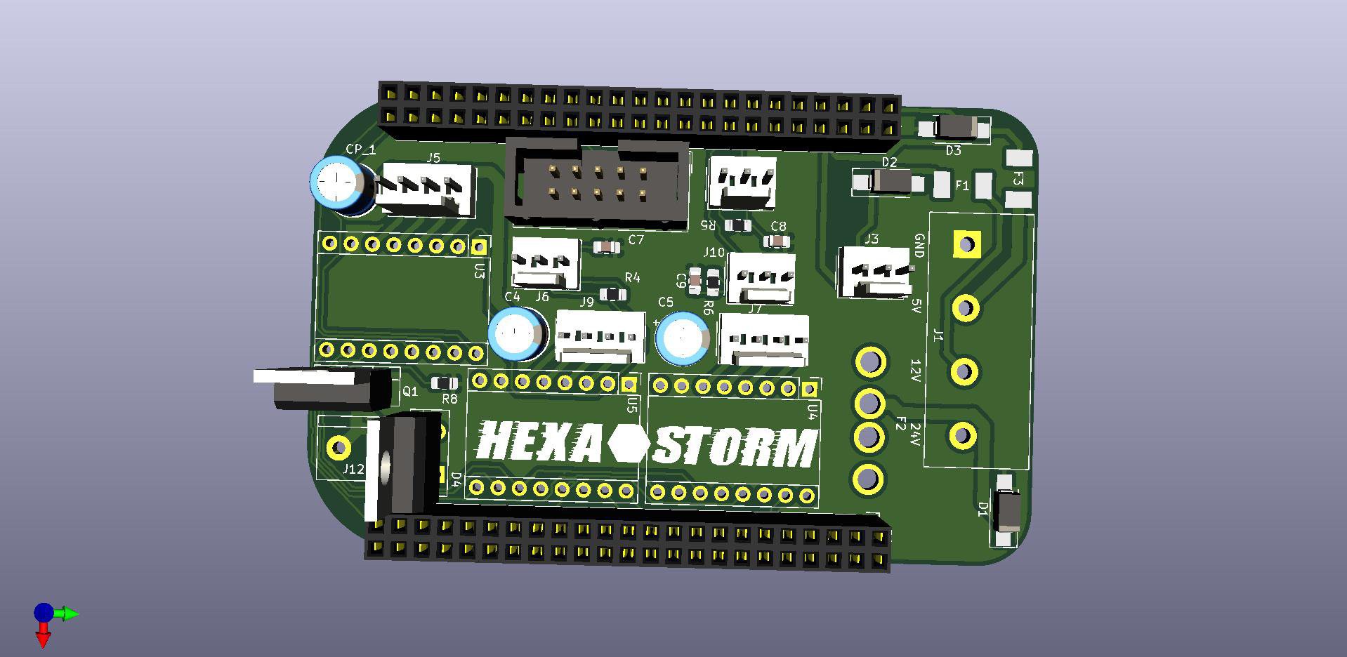
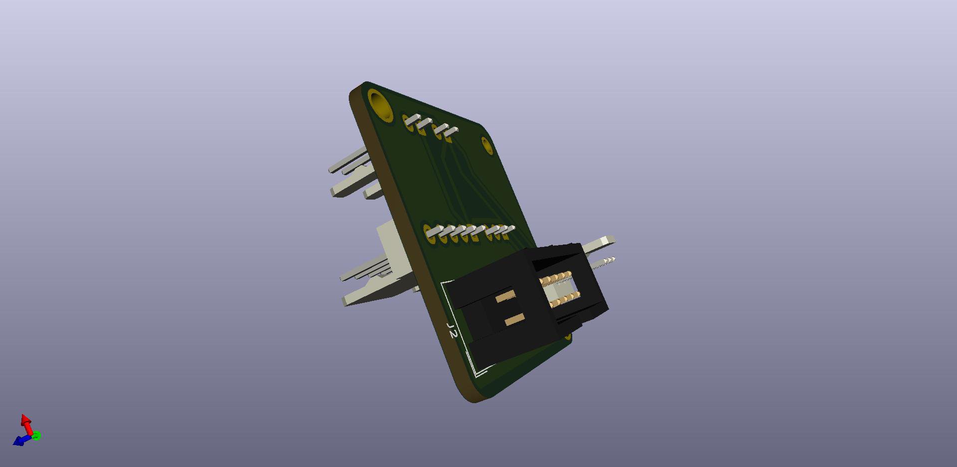
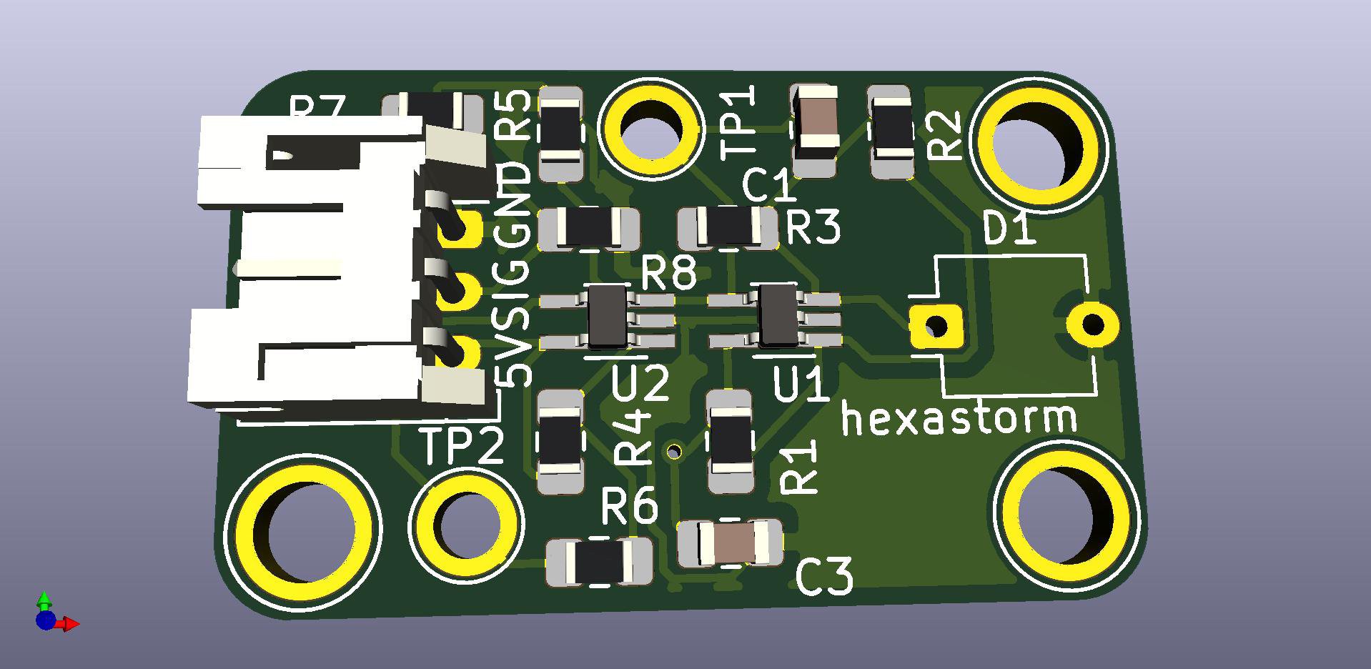
I have made three PCBs; beaglebone cape, laser module pcb, end of stopline pcb.
This should have the following advantages;
- Photodiode is read out with amp and Schmith trigger
- Laser scan head can easily be detached from machine
- Electrical wiring to the laser are kept short. The anode and kathode of the laserdiode are not exposed outside of the scan head. Damage is prevented and electrical noise minimized.
- The scanhead is a separate entity from the cape. The scanhead could be interfaced by other boards. The scanhead can also be detached to place it into a different setup.
The Beaglebone cape is shown below. The main board can be connected to three stepper boards, three endstops, the spindle controller and the scanhead via a 10 pin cable.

The Beaglebone cape talks to the scanhead via 10 pins. The scanhead also needs three power lines. The power is provided via the Firestarter cape as there are some safety measures present there.
The scanhead board has two sides in and out, so one can connect to the components in the scan head.

The PCB for the for the photo-diode with the op amp and the Schmitt trigger is shown below

Boards are submitted for order via PCB way. Total costs for 3x 5 boards plus shipping is 38 dollars.
 Hexastorm
Discussions
Become a Hackaday.io Member
Create an account to leave a comment. Already have an account? Log In.