I balanced a prism using the single-plane 2 run method.
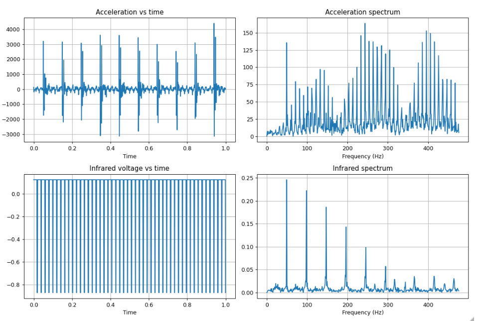
Let's look at a plot of the polygon motor with AN44000A chip and an unbalanced 30x30x2 mm square prism.
 A clear peak is present at 50 Hertz for both the acceleration and infrared spectrum.
The rotor is pulsed at a frequency of 10 Hertz. It apparently spins five times faster.
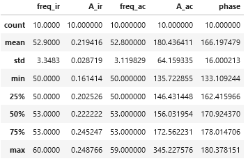
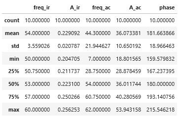
Before adding a weight the following measurements are obtained;

Mirror motors have 5 pins; PWM, MOTOR_EN, GND, Voltage and LCK_PIN.
PWM is speed control. GND is ground. Voltage is the supply voltage, ideally 24V. LCK_pin is
false if encoder and signal are not in sync. I cannot confirm the function of LCK_pin and MOTOR_EN.
Changing them or looking at their input does not reveal any activity.
I will try to expose with the AN44000A. So far I only exposed with NBC31111.
Finally, Max who bought the first prisms found some interesting links.
Baraja
Baraja is building a LIDAR scanner which uses a prism with an uneven number of facets.
They do not rotate the prism but change the frequency of the laser.
https://www.baraja.com/
DIY linear motor
There is an instructable of someone who build a DIY linear motor. In the first machine with a prism scanner a linear motor was used.
https://www.instructables.com/DIY-IRONLESS-LINEAR-SERVO-MOTOR/
 Hexastorm
Discussions
Become a Hackaday.io Member
Create an account to leave a comment. Already have an account? Log In.
Just curious but would it help any to have a motor driver that compensated for being slightly out of balance?
Are you sure? yes | no