I did experiments with the new bearing.
Results so far;
- rotation can be achieved vertically;
ferrite is added below the PCB. The magnets in the rotor are pulled toward the ferrite
As such, the rotation axis does not have to be parallel with gravity.
The motor is more than powerful enough to overcome the additional friction.
- on small time scales, i.e. less than 10 facets/lines, the cross scan error is low on longer time scales ,
i.e more than 30 facets. The cross scan error is high.
For small time scales, the cross scan error seems good enough for exposure.
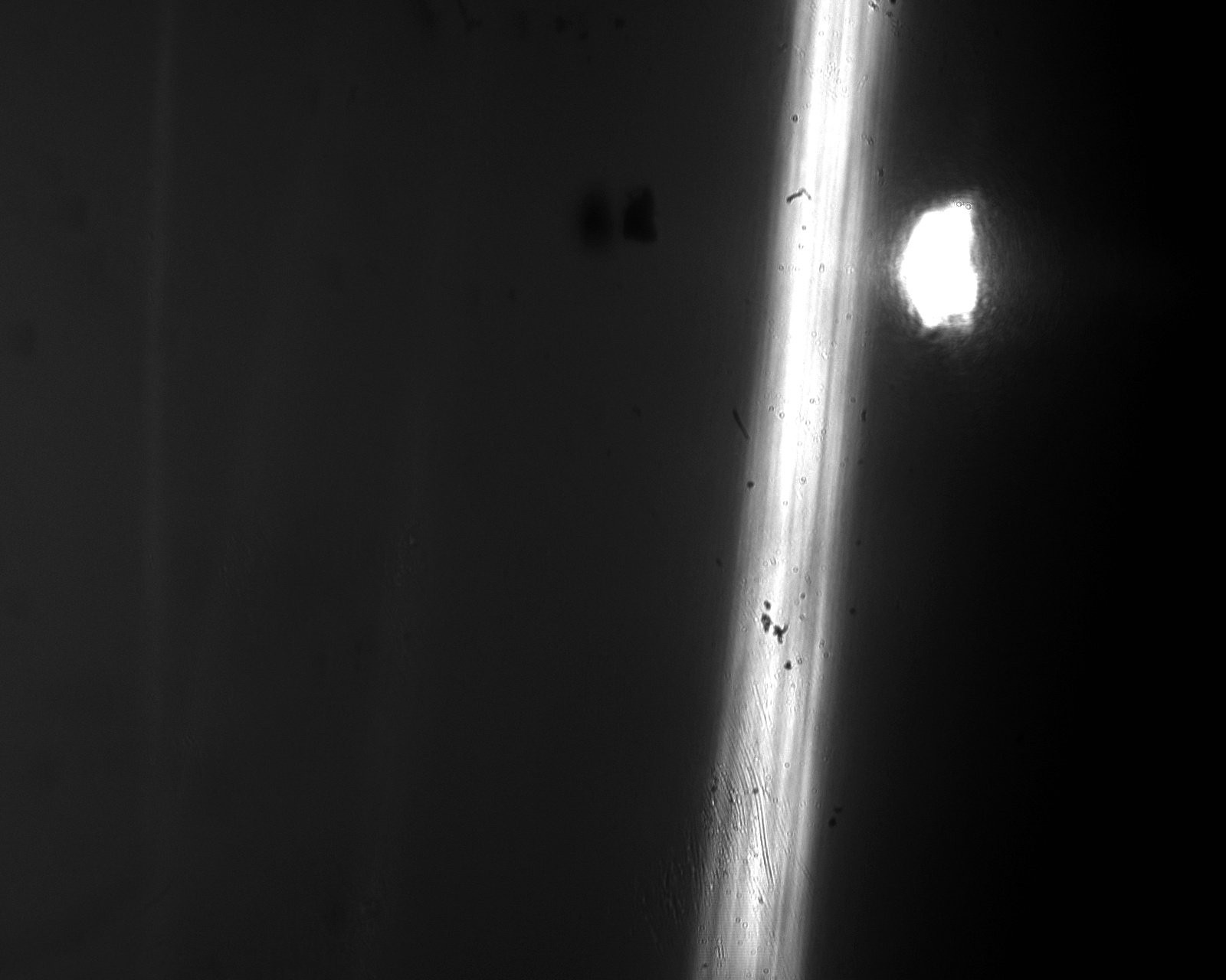
An image at a short time scale, i.e. less than 10 lines in image.

An image of a long time scale,

The spot on the side is as not all light is refracted through the prism or due to some internal reflection.
This is easy to fix by either a slit or changing the thickness of the prism. As such it is disregarded.
From additional research, I conclude that you are indeed looking at a vibration. This vibration is likely due to particles or dusts between the axis and the bearing.
I shortened the pole and still saw this behavior (see next blog). The noise removed after adding a bit lubricant.
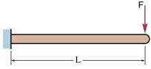
I also expect that part of the error can be explained via an end-loaded cantilever beam:
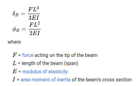
 This displacement and angular deflection are described by the following formula;
 The centripetal force rises with the square of the speed. As such, I have two methods to test this theorem;
- reduce the speed
- decrease the beam length
Calculating the first natural frequency of the beam and see if this is in the time domain of 30 lines.
I arrived at multiple kHz. Probably, the treatment is too simple.
Experimental notes:
Speed around 1000-2000 RPM
Length extracted is 13.75 mm
Length used in this experiment 18.8 mm
 Hexastorm
Discussions
Become a Hackaday.io Member
Create an account to leave a comment. Already have an account? Log In.