 Hexastorm
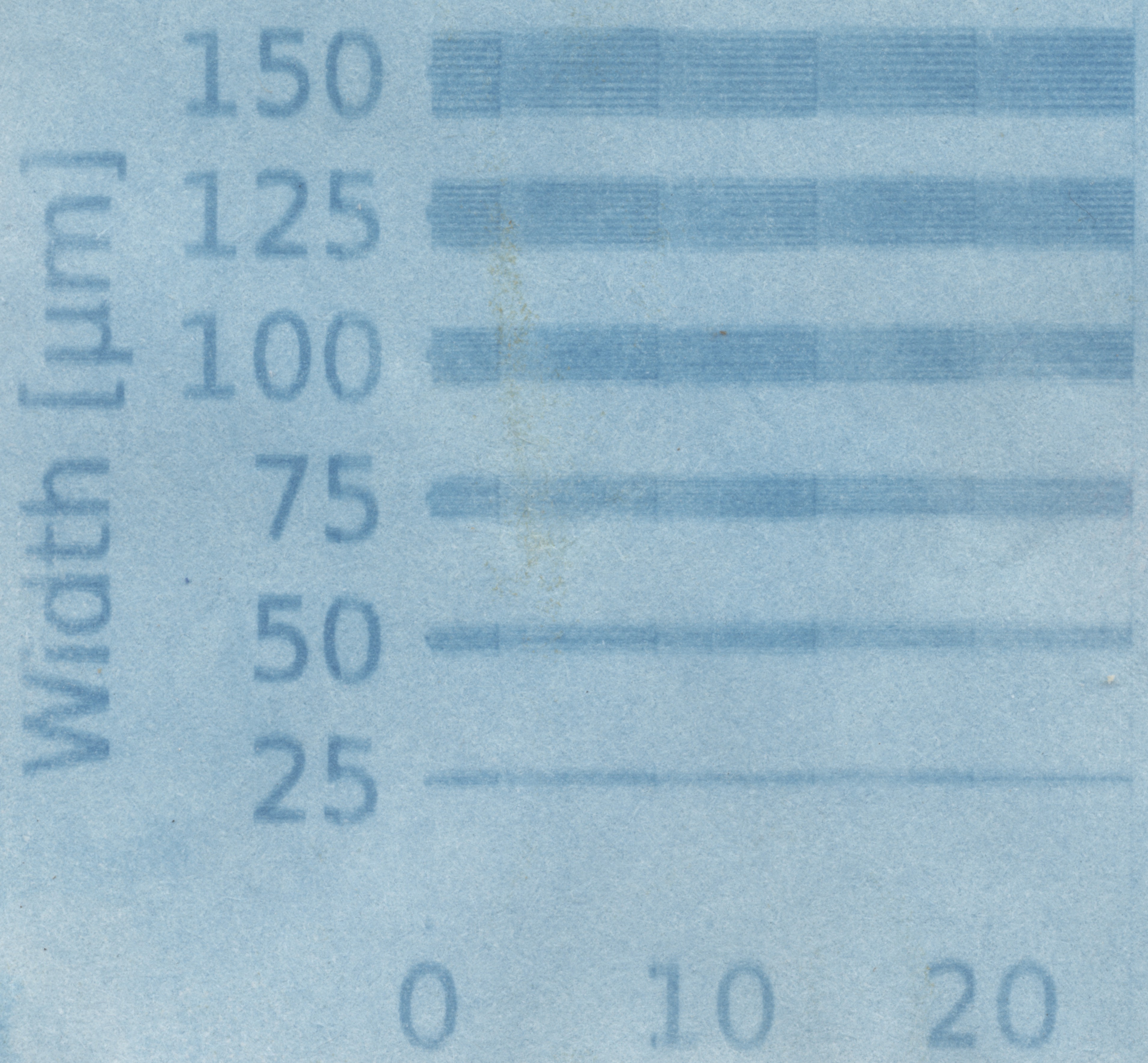
In the following images, the scan direction is along the x-axis direction. Lines are projected parallel to this direction. As such, the error in the y-axis represents the cross scan error. Substrate is solar-fotopapier, 20 blatt, format 14x19 cm. Using a scissor I cut a good sized rectangle (4x4 cm)
Each line is exposed four times at a rate of 3000 RPM, i.e. 12000 facets per minute. Laser current is assumed to be 500 mA.
Using a single facet
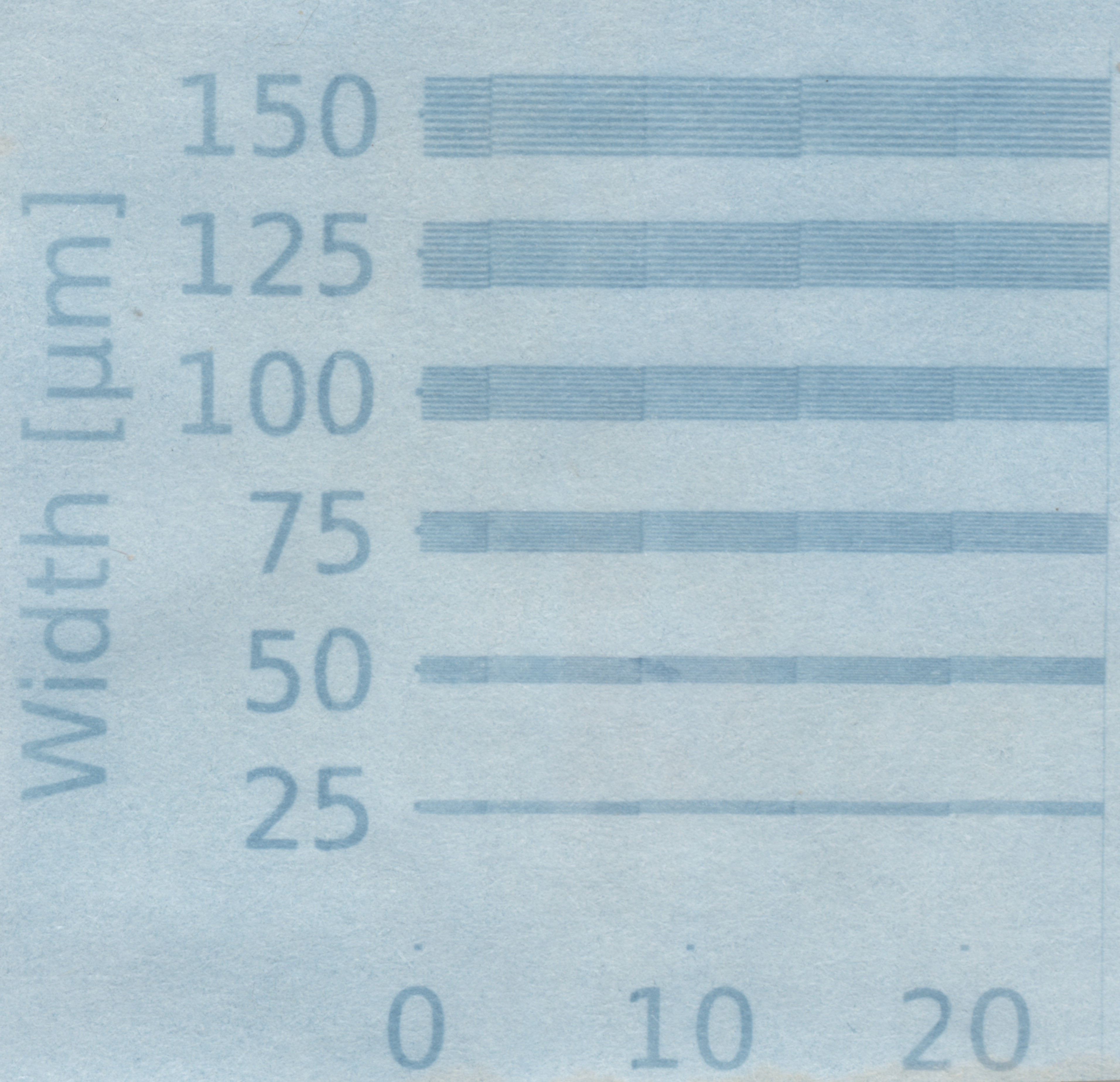
With a single facet lines are much sharper and 75 micron seems achievable. Stitching between lanes is a challenge as well. Odd lane (backward) have an other offset than even lanes (stage moves forward).
Gravis pointed out that potentially, an algorithm, which takes the facet number into account could correct for the cross scan error. This is easy to imagine and can be executed, it is just hard to do so.
Patterns is created via python, see crosscantest in https://github.com/hstarmans/hexastorm/blob/master/src/hexastorm/interpolator/patterns/create.py . In the pictures, on the left axis you see the lane width. There are ten lines per group where width and spacing are equal to the number denoted e.g. 50 microns. On the x-axis the distance between 0 and 10, is 10 mm. It just measures actual distance along x axis.
Discussions
Become a Hackaday.io Member
Create an account to leave a comment. Already have an account? Log In.